Continue to Site

Welcome to our site!

Electro Tech is an online community (with over 170,000 members) who enjoy talking about and building electronic circuits, projects and gadgets. To participate you need to register. Registration is free. Click here to register now.

  • Welcome to our site! Electro Tech is an online community (with over 170,000 members) who enjoy talking about and building electronic circuits, projects and gadgets. To participate you need to register. Registration is free. Click here to register now.

Switching relay with a pic?

Status
Not open for further replies.

Jerran

New Member
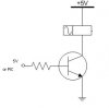
Im trying to trigger a 5 volt relay with a Pic and cant seem to figure out how to do it. The simplest solution I though of was to use a 2N2222 npn transister as an on off switch between the relays coil and ground(one side of the coil wired to the battery obviously), hit the base with a pulse from my pic and presto a programmable timing relay. Long story short it worked better on paper :)

The transistor works(aka switches) if I touch its base with a wire from +5V but the pic isnt able to trigger it. Ive tried a mosfet inplace of the transistor and nothing happens. Usually the mosfet fires 1 time and thats it, I wired a led between the fets gate and my output pic pin and it is lighting up and dims so it isnt that my pic isnt creating a voltage/current. Possible Im wiring the fet incorrectly because after its initial(and only) firing from my pic I can touch its metal sink and make the relay trigger, but Ive used fets in pwm circuits and Ive wired them just as this one is.

Ive tried pull up resistos, pull down resistors but nothing seems to help. Does anyone have a better solution or see a flaw in my design?

additional Info.
powered by 9 (also tried regulated 5 from 6) regulated to 5 volts
12f675 pic
2n2222 transistor and/or N channel power mosfet
5 volt relay with 56 ohms resistance coil at 90 mA max current
regulator is a 7805 3 pin Reg
 
Response time

Yes, you are right to select 2N2222 transistor because it is used main for switching purpose. Such as to trigger a relay due to maximum allowable collector current is 1Am.
As shown in the figure, when 5V is applied to the base through R1, then the relay will trigger. The 5V can be from PIC or other power source with proper ground.
If you said you did touch the base with 5V and the relay can trigger then this is likely due to the fact of you program. Or, you can check the output voltage of that pin you use to trigger the relay. If you want to hit the base with a pulse then you should consider the relay response time because of the relay response time. It won’t trigger if the pulse width duration is 1us or even 1ms. A significant output should be 1 second or more.

In addition, most properly to trigger a relay, we don’t use MOSFET cause it is for fast switching and high power… :idea:
 

Attachments

  • SwitchingCircuitry.JPG
    SwitchingCircuitry.JPG
    5.9 KB · Views: 1,209
Don't forget to put a diode in reverse over the relay to absorb the energy of the coil when switched off.
 
Ive got it simi working now. The circuit works well till I touch the board or a shielded part of a component. I think Im having grounding problems on my proto-board. Touching the pic or my regulator seems to make the pic behave oddly, mainly in that it starts firing the relay in pulses. Is it a good idea to ground all my unused pins on the PIC when they arnt in use? Atm my trisio is set so that only pin 1 is output and the other unused pins are set to inputs.
 
If not in use I would put all unused pins as outputs just in case.

:arrow: Make soure you have the right caps to filter out the noise. A 0.1uF at the 5V pin in the PIC to ground is necesary to avoid funky stuff, a

:idea: a 4.7K pull up resistor for the MCRL is a very good idea.

:arrow: Remember that if the relay is power from the same 5V, the relay will put some noise on the line...

:idea: Connect the relay power as close as possible to the 5V power supply.... don't just get a wire from the 5V pin of the PIC. Get the power straigt from the 7805 output pin, and the same with the ground.

:!: And as Exo mentioned before, don't forget to put a reverse biased diode across the relay leads.

Ivancho
 
The problem has to be with my code or my pic. I posted my code to see if you see a problem in it while I dig out some caps to make an external clock(currently using the internal clock and confirmed its functioning by replacing the transistors base at pin 1 with a led+resistor)
Low 0
Low 2
Low 4
Low 5

loop: High 1
Pause 10000
Low 1
Pause 10000
Goto loop
End
 
Awesome, the pull up resistor on MCLR did the trick. Ive tried all but licking the board(jk hehe) and cant get it to act spuratic as it did before.

Thanks a ton for the help :)
 
You cant pull all the unused pin to ground.

If you declare all pins as Output then you not need to pull it to ground and thus can save your components.

We normally pull input pin to ground when it is connected to switch because the PIC understand only logic 0 or logic 1. Cant leave input pin free.[/list][/list]
 
We normally pull input pin to ground when it is connected to switch because the PIC understand only logic 0 or logic 1. Cant leave input pin free

i have just had a problem with my pic in testing with a switch on one of the PORTA's on a 16F84A

i used the BTFSS command

and connected a switch from +5v to RA0 however no matter wether the switch is closed or open the led's alway seem to come on!

so is this a problem with the switch "floating"?

and how should i pull it to ground?

Thanks
 
thanks exo it worked a treat!

looks like i ask too many questions ....next time tell me to shut up :p

:lol:

Kane
 
Cool thanks for the info Monkeyxp. I knew it was good practice to ground unused pins of cmos chips but wasnt sure about pics.
 
Status
Not open for further replies.

New Articles From Microcontroller Tips

Back
Top