Continue to Site

Welcome to our site!

Electro Tech is an online community (with over 170,000 members) who enjoy talking about and building electronic circuits, projects and gadgets. To participate you need to register. Registration is free. Click here to register now.

  • Welcome to our site! Electro Tech is an online community (with over 170,000 members) who enjoy talking about and building electronic circuits, projects and gadgets. To participate you need to register. Registration is free. Click here to register now.

Switching regulator - excessive current consumption

Status
Not open for further replies.

nickagian

Member
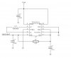
For a project with a microcontroller, I am using TPS63031 switching regulator from TI to convert the voltage from a Li-ion battery to a +3.3V dc stabilized power supply. During time, the microcontroller wakes up, takes samples from some sensors and then goes to sleep, then wakes up again and so on. During sleep periods, most of the ICs of the board are switched off (but not the regulator).

The problem is the following : I have noticed that when the current consumption of the board during the active periods is above or around 50mA, then during the following sleep period the current consumption is around 5.5mA. However, if the active current consumption is below 50mA more or less, then the sleep current is around 700uA. Except for the difference in the active current, there is no other difference between the two cases. The same ICs are supplied during sleep for both cases. I assume that the majority of this current is consumed at the regulator. However, I cannot understand

(1) why this difference exists and
(2) why the current is so high.

Theoretically, the current consumption of the rest electronics (except for the regulator) during the sleep periods should be around 200uA or less. Thus, I would expect that the total current consumption (with the regulator) would be around 500uA or so. Can anyone help me with this weird problem?
 
What is the PS/SYNC pin connected to?
 
Actually I do not have a schematic right now available, but I could post something tomorrow.

The PS/SYNC pin is connected to GND, in order to enable power save mode and EN is tied to VIN (regulator always enabled). The actual value of the efficiency, however, is such that seems as if the power save mode was disabled, which is not true.

Nevertheless, I am thinking of something : The PCB does not have a separate ground plain for the power ground of the regulator. Could this cause such a problem described in my previous post?
 
Last edited:
I don't think it's related to the ground plane.

It is indeed a puzzle, why the sleep current should be affected by the current it sees during normal operation. Can't think of any reason for that. It's as if it has a memory for it's previous operation.

Can you measure it's output current during the sleep period to verify that there is no load current?
 
Here is the schematic of the connections for the regulator.

Unfortunately, I cannot measure the output current of the regulator (I haven't left any Test Point on the PCB). But I will try to see which ICs are under voltage during the sleep period and could possibly draw current.
 

Attachments

  • pp.JPG
    pp.JPG
    21.1 KB · Views: 214
Here is the schematic of the connections for the regulator.

Unfortunately, I cannot measure the output current of the regulator (I haven't left any Test Point on the PCB). But I will try to see which ICs are under voltage during the sleep period and could possibly draw current.

nice chip... only thing i see off hand is you need to take out the 100 ohm resistor
 
Why do you think this 100 ohm resistor is a problem?
 
Why do you think this 100 ohm resistor is a problem?

there is a resistor internal to the chip, at best it is not required. how are you connecting to the chip? it looks like it will run hot at load with out heat sinking. (4.5V @ 0.8A @ 80% eff ... thermally it says 60C/W assuming a thermal clad PCB)
 
there is a resistor internal to the chip, at best it is not required.
I see... I guess I'll replace it with a zero-ohm resistor and hope it does make a difference...

how are you connecting to the chip? it looks like it will run hot at load with out heat sinking. (4.5V @ 0.8A @ 80% eff ... thermally it says 60C/W assuming a thermal clad PCB)
I am not quite sure I understand what you're asking, but nevertheless the chip is populated on the PCB with its PowerPAD soldered (if this is what you mean). Do you think this is not enough and thus normal operation is affected by the heat? To tell you the truth, the possibility of overheating is something I haven't thought of so far. And in fact, I don't know of any way to improve the power dissipation capability...

One more -maybe stupid- question : Is it possible that the switching currents flowing through ground plain can cause the voltage level of ground to rise slightly above zero and thus disabling the power save mode of the chip? The max input low voltage for the PS/SYNC pin is 0.4V. Of course, this case is not observed when measuring with the voltmeter during operation, but I don't know what else to think of.
 
Last edited:
I see... I guess I'll replace it with a zero-ohm resistor and hope it does make a difference...
NO!!!! JUST REMOVE IT!!!!
I am not quite sure I understand what you're asking, but nevertheless the chip is populated on the PCB with its PowerPAD soldered (if this is what you mean). Do you think this is not enough and thus normal operation is affected by the heat? To tell you the truth, the possibility of overheating is something I haven't thought of so far. And in fact, I don't know of any way to improve the power dissipation capability...

One more -maybe stupid- question : Is it possible that the switching currents flowing through ground plain can cause the voltage level of ground to rise slightly above zero and thus disabling the power save mode of the chip? The max input low voltage for the PS/SYNC pin is 0.4V. Of course, this case is not observed when measuring with the voltmeter during operation, but I don't know what else to think of.

generally not ... what is more common is that the generated noise wreaks havoc with the regulator stability
 
NO!!!! JUST REMOVE IT!!!!
But if I remove it completely, how will the regulator be enabled? Shouldn't the 'EN' pin be at high logic voltage? I'm sorry, maybe I'm missing something...
 
Ok, as stupid as it may be heard, but the reason for this problem was this: I was using the TPS63031 on a PCB with a footprint designed for a TPS63001 (the PCB designer has made a mistake on this). And TPS63001 is a little bit bigger than the TPS63031. Thus, obviously some leakage current is flowing and is causing this high current consumption. Thank you for your help and sorry for the stupidity of the reason... :(
 
Status
Not open for further replies.

New Articles From Microcontroller Tips

Back
Top