Continue to Site

Welcome to our site!

Electro Tech is an online community (with over 170,000 members) who enjoy talking about and building electronic circuits, projects and gadgets. To participate you need to register. Registration is free. Click here to register now.

  • Welcome to our site! Electro Tech is an online community (with over 170,000 members) who enjoy talking about and building electronic circuits, projects and gadgets. To participate you need to register. Registration is free. Click here to register now.

switching circuit

Status
Not open for further replies.

tinytimy

New Member
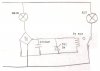
Hello, I have a project where i have to create circuit that works as follows: There is two lamps(1 lamp is replacement lamp), when turn circuit on, active lamp lights up, but when the lamp burns out, replacement lamp lights up.
My problem is that I dont know how to make a switching and circuit is designed to work with an AC 220V 50Hz 60W lamps.

I have found so far that of the switch i can use thyristor or relay but if i use relay it switch and then turns of, because if it is turned on or there will be magnetic field what will make problems with the antenna what is really important.
What i want from people of this forum: what can you recommend, how to realize this?!
Thank you for your attention

p.s if you think for what i need this type of circuit, it is for safety because there must be light all night.
 
Can you just use more than one on at a time?
May first thought would be to use a on at night controler.
Right next to the primary light so if it goes out the backup will turn on because its dark.
 
....I have found so far that of the switch i can use thyristor or relay but if i use relay it switch and then turns of, because if it is turned on or there will be magnetic field what will make problems with the antenna what is really important....
What is the antenna for? RF radiation from thyristor triggering may be more of a problem than the magnetic field from a relay...depending on what the antenna is for.

Ken
 
**broken link removed**
my idea are like this use Single Power Supply comparator for voltage compere, when L1 lamp is lit comparator will not turn on thyristor, but when lamp L1 burned out , comparator will turn on thyristor and lamp L2 will light up, question:
1)is this circuit correct and will this circuit work how i want to?! if no what wrong with this circuit.

Thank you for your attention.
 
I hope that circuit is only a concept, because in practice it's a disaster. Again, what is the "antenna" you referred to? I have an idea but need to think about it.

Ken
 
OK. Are the lamps, or their 220VAC wiring, anywhere near the antenna? Are lamp dimmers used around the antenna, feed lined or receiver. I have an idea (attached), but uses a triac. These are the noisest (RF wise) when that are partially on. My circuit would have it either on or off.

The attached circuit is just off the top of my head. When I1 is ON, the current through R1 generated a voltage that drives Q1 and shorts out the LED in U1. If I1 burns out, Q1 turns off and allows the LED in U1 to turn on and trigger the triac ON, so I2 lights. This is untried and the component values are estimates.

It might be modified so Q1 drives a relay that controls I2. Maybe Ill add that.

Ken

LightSwitch.gif
 
To know if the first bulb is good you really need to monitor the current flow in the bulb.
I would consider a current transformer in series with the first bulb. If there is current flow then the second bulb is off. If no current flow the second bulb in on.

The attached data sheet shows a part that will create a small voltage if there is current. (in the first bulb)
 

Attachments

  • sen60.pdf
    263.6 KB · Views: 158
OK. Attached is a relay version. The current transformer is a good possibility, but the lamp current is only 270mA. That one's spec ends at 15mV/1A.
Ken

LightSwitch2.gif
 
Another option is to just put a low voltage relay in series with the main lamp. If you get an AC relay, you can just connect its coil in series with the lamp, and place a resistor in parallel with the coil to shunt the excess current. If you get a DC relay, you can add a rectifier and filter (circuit attached).
 

Attachments

  • alt lamp.jpg
    alt lamp.jpg
    31.9 KB · Views: 162
Aircraft warning lights often have 3 or 4 bulbs, if one goes theres no significant change, you could monitor them all and bring on a warning if one fails.
If one is on and one off, and the light is really imprtant you also should pass a small current (not enough to light it) through the bulb thats off to indicate that the filament and wiring is actually ok and the lamp would light if required (this is probably why aircraft beacons have several lamps on at once).
 
OK. Are the lamps, or their 220VAC wiring, anywhere near the antenna? Are lamp dimmers used around the antenna, feed lined or receiver. I have an idea (attached), but uses a triac. These are the noisest (RF wise) when that are partially on. My circuit would have it either on or off.

The attached circuit is just off the top of my head. When I1 is ON, the current through R1 generated a voltage that drives Q1 and shorts out the LED in U1. If I1 burns out, Q1 turns off and allows the LED in U1 to turn on and trigger the triac ON, so I2 lights. This is untried and the component values are estimates.

It might be modified so Q1 drives a relay that controls I2. Maybe Ill add that.

Ken

View attachment 86000
yes, dimmers will be used around antenna and feed lined. :)
thanks for the replies, it allows me to move on to the target
 
Use an LED, 100,000 hours burn time means you dont need to worry about failiure, not for a long time anyway.
 
Status
Not open for further replies.

New Articles From Microcontroller Tips

Back
Top