Continue to Site

Welcome to our site!

Electro Tech is an online community (with over 170,000 members) who enjoy talking about and building electronic circuits, projects and gadgets. To participate you need to register. Registration is free. Click here to register now.

  • Welcome to our site! Electro Tech is an online community (with over 170,000 members) who enjoy talking about and building electronic circuits, projects and gadgets. To participate you need to register. Registration is free. Click here to register now.

Switcher CAD III help

Status
Not open for further replies.

zachtheterrible

Active Member
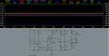
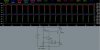
I know that I am probably doing something stupid, but I've built a transmitter circuit. The thing is, when I try and see the oscillations, all that I get is a straight line. I am testing in the right spot . . . in the middle of LC.
When I select skip initial operating point solution, I see a wave for just a second, and then it dissapears and all I see is a straight line. WHAT IS GOING ON!?!?!? :x

Also, what is a floating node??
 
Post your schematic. You can do this easily by:
1. Scaling the window to an appropriate size
2. Click on Tools/Copy bitmap to clipboard
3. Paste into something like Paint
4. Save as a .gif or .jpg
5. Use "Add attachment" on this board and browse to the file you just saved.

Maybe you already knew that.

A floating node is one that has infinite resistance to GND, such as the end of a dangling component, or the junction of two series capacitors. If you have a legitimate case like this, you can add a LARGE resistance to GND, like 1e12 (10^12) ohms.
 
Here they are. If someone would be so kind as to supply me w/ an email address, I could send the .asc to someone. panic mode, you said to post the asc . . . that's a program, not a picture, so how could I post it?? I made this LED flasher on the CAD program, and it worked great. Thats the only thing that has worked though. what am i doing wrong?

Btw, does anyone know what happened to this website yesterday? When I tried to get on, it said:

404- Gh0st not found
Admin- sux

What gives?
 

Attachments

  • fm_transmitter_cad.jpg
    fm_transmitter_cad.jpg
    61.1 KB · Views: 341
  • led_flasher_cad.jpg
    led_flasher_cad.jpg
    61.1 KB · Views: 327
asc is just a short text file, not as compact as SPICE Netlist but close enough.
 
btw, I see your schematic is missing capacitors between mic and Q1,
and between Q1 and Q2. Also 1ms is not quite long time. Some
oscillators are slow (like this one) so try changing transition time to 3ms for example. Btw here is ASC file I created:
Code:
Version 4
SHEET 1 880 680
WIRE -464 48 -464 -32
WIRE -464 -32 -96 -32
WIRE -96 -32 -96 16
WIRE -96 -32 -16 -32
WIRE 64 -32 176 -32
WIRE 528 -32 528 128
WIRE 432 128 432 -32
WIRE 432 -32 528 -32
WIRE 240 48 240 -32
WIRE 240 -32 432 -32
WIRE 176 160 176 -32
WIRE 176 -32 240 -32
WIRE -96 96 -96 160
WIRE -64 160 -96 160
WIRE -96 160 -96 304
WIRE -96 160 -208 160
WIRE -208 304 -208 352
WIRE -160 352 -208 352
WIRE -208 352 -208 432
WIRE -176 576 -96 576
WIRE 496 576 496 544
WIRE 240 544 240 576
WIRE 240 576 496 576
WIRE 176 496 176 576
WIRE 176 576 240 576
WIRE -208 576 -208 496
WIRE -208 576 -464 576
WIRE 0 160 32 160
WIRE 32 160 32 352
WIRE 32 352 176 352
WIRE 176 224 176 352
WIRE 176 352 240 352
WIRE 240 464 240 352
WIRE 240 352 336 352
WIRE 176 352 176 432
WIRE 240 352 240 128
WIRE 432 192 432 256
WIRE 432 256 528 256
WIRE 528 256 528 208
WIRE 528 320 528 256
WIRE 400 400 400 432
WIRE 400 432 496 432
WIRE 496 464 496 432
WIRE 496 432 528 432
WIRE -464 -32 -656 -32
WIRE -784 -32 -784 272
WIRE -784 352 -784 576
WIRE -464 128 -464 352
WIRE -464 352 -416 352
WIRE -656 112 -656 -32
WIRE -656 -32 -784 -32
WIRE -656 176 -656 576
WIRE -656 576 -784 576
WIRE -208 160 -208 224
WIRE -352 352 -208 352
WIRE -176 624 -176 576
WIRE -176 576 -208 576
WIRE -96 400 -96 576
WIRE -96 576 176 576
WIRE -464 352 -464 448
WIRE -464 528 -464 576
WIRE -464 576 -656 576
WIRE 528 432 528 384
WIRE 432 256 400 256
WIRE 400 256 400 304
FLAG -176 624 0
SYMBOL npn -160 304 R0
SYMATTR InstName Q1
SYMATTR Value 2N3904
SYMBOL npn 336 304 R0
SYMATTR InstName Q2
SYMATTR Value 2N3904
SYMBOL ind 512 112 R0
SYMATTR InstName L1
SYMATTR Value 33µH
SYMBOL cap -672 112 R0
SYMATTR InstName C1
SYMATTR Value 0.1µF
SYMBOL cap -352 336 R90
WINDOW 0 0 32 VBottom 0
WINDOW 3 32 32 VTop 0
SYMATTR InstName C2
SYMATTR Value 0.47µF
SYMBOL cap -224 432 R0
SYMATTR InstName C3
SYMATTR Value 4.7nf
SYMBOL cap 0 144 R90
WINDOW 0 0 32 VBottom 0
WINDOW 3 32 32 VTop 0
SYMATTR InstName C4
SYMATTR Value 0.047µF
SYMBOL cap 160 160 R0
SYMATTR InstName C5
SYMATTR Value 510p
SYMBOL cap 160 432 R0
SYMATTR InstName C6
SYMATTR Value 10nF
SYMBOL cap 416 128 R0
SYMATTR InstName C7
SYMATTR Value 100p
SYMBOL cap 512 320 R0
SYMATTR InstName C8
SYMATTR Value 45p
SYMBOL res -480 32 R0
SYMATTR InstName R1
SYMATTR Value 15k
SYMBOL res -224 208 R0
SYMATTR InstName R2
SYMATTR Value 330k
SYMBOL res -112 0 R0
SYMATTR InstName R3
SYMATTR Value 3.3k
SYMBOL res 224 32 R0
SYMATTR InstName R4
SYMATTR Value 10k
SYMBOL res 224 448 R0
SYMATTR InstName R5
SYMATTR Value 2.2k
SYMBOL res 480 448 R0
SYMATTR InstName R6
SYMATTR Value 470
SYMBOL res 80 -48 R90
WINDOW 0 0 56 VBottom 0
WINDOW 3 32 56 VTop 0
SYMATTR InstName R7
SYMATTR Value 100
SYMBOL voltage -784 256 R0
WINDOW 123 0 0 Left 0
WINDOW 39 24 132 Left 0
SYMATTR SpiceLine Rser=1
SYMATTR InstName V1
SYMATTR Value 9
SYMBOL voltage -464 432 R0
WINDOW 123 0 0 Left 0
WINDOW 39 0 0 Left 0
SYMATTR InstName V2
SYMATTR Value SINE(0 0.010 1000)
TEXT -818 586 Left 0 !.tran 3ms
 
That was one of the STUPIDEST things that I have ever done!!!!!!!! I thought that putting in 1 meant putting in 1 second, not millisecond!!!
stupid stupid stupid stupid stupid stupid stupid stupid stupid


btw, thanx :D
 
Status
Not open for further replies.

Latest threads

New Articles From Microcontroller Tips

Back
Top