Hi guys,
I've been working on a project that powers a device which averages about 600mA at 12V but fluctuates and peaks at about 4A but for very short periods of time especially when starting up. While it runs on batteries most of the time I am wanting it to run from a 240v source from time to time and as such I've devised a 240v / battery power module with a basic relay to switch between the two automatically.
The issue
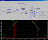
I have a 12V 5A switchmode PSU in play and while it works fine 90% of the time, sometimes (only when a cold start situation) the PSU just cant handle it and instead of firing up it will start flickering the power and putting my multimeter on it I'm getting random hz from 1 to 200Hz output and low voltage. and unless I dissconnect it, it will never get to providing the good 12V source my device requires. Sometimes it will work if I turn off the load device and let the PSU get its act together then turn them on, but even then only half the time that will work.
When switching from battery to power it seems to be fine I guess as the Caps in the device are already charged or something.
My question is, would a traditional coil based transformer stop this from happening? I am at my wits end.
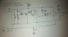
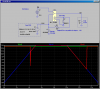
I did design a new schematic as I thought the original cause was the relay chatter from the sudden voltage drop, so I designed a different schematic to route the power from the transformer via a big diode (stopping battery feedback during battery operation) and used the relay to simply isolate the battery when on Transformer power. This worked in testing and theory but as the issue isn't about the relay chatter it is still a major problem.
Any help is greatly appreciated!
Thanks
I've been working on a project that powers a device which averages about 600mA at 12V but fluctuates and peaks at about 4A but for very short periods of time especially when starting up. While it runs on batteries most of the time I am wanting it to run from a 240v source from time to time and as such I've devised a 240v / battery power module with a basic relay to switch between the two automatically.
The issue
I have a 12V 5A switchmode PSU in play and while it works fine 90% of the time, sometimes (only when a cold start situation) the PSU just cant handle it and instead of firing up it will start flickering the power and putting my multimeter on it I'm getting random hz from 1 to 200Hz output and low voltage. and unless I dissconnect it, it will never get to providing the good 12V source my device requires. Sometimes it will work if I turn off the load device and let the PSU get its act together then turn them on, but even then only half the time that will work.
When switching from battery to power it seems to be fine I guess as the Caps in the device are already charged or something.
My question is, would a traditional coil based transformer stop this from happening? I am at my wits end.
I did design a new schematic as I thought the original cause was the relay chatter from the sudden voltage drop, so I designed a different schematic to route the power from the transformer via a big diode (stopping battery feedback during battery operation) and used the relay to simply isolate the battery when on Transformer power. This worked in testing and theory but as the issue isn't about the relay chatter it is still a major problem.
Any help is greatly appreciated!
Thanks
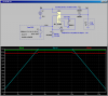
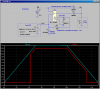
 are you referring to this style of setup?