Continue to Site

Welcome to our site!

Electro Tech is an online community (with over 170,000 members) who enjoy talking about and building electronic circuits, projects and gadgets. To participate you need to register. Registration is free. Click here to register now.

  • Welcome to our site! Electro Tech is an online community (with over 170,000 members) who enjoy talking about and building electronic circuits, projects and gadgets. To participate you need to register. Registration is free. Click here to register now.

Super simple VCO is surprisingly linear

Status
Not open for further replies.

Gasboss775

Member
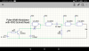
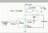
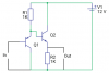
I seen something like this online and decided just to try it out. Was surprised that it is fairly linear. Not up to the standard of say an lm331 but for such a simple circuit pretty good. Also the sawtooth waveform ( descending ramp ) is also pretty linear over the full range of the vco. By adding a monostable to the pulse output you could get voltage controlled pwm. I expect it would drift with temperature, though there are probably ways of compensating for that, but that would be contrary to the principal appeal of the circuit, that it is very simple!
 

Attachments

  • 4093 Schmitt Nand based VCO.png
    4093 Schmitt Nand based VCO.png
    74.5 KB · Views: 1,170
I expect it would drift with temperature, though there are probably ways of compensating for that, but that would be contrary to the principal appeal of the circuit, that it is very simple!
You have already said it. There are no ways to thermally stabilize CMOS, there is also large variety of them.
 
PWM augmentation with range of 2 - 93% duty cycle over 0.5 - 15 volt control voltage input
 

Attachments

  • Screenshot_2016-01-02-20-19-06.png
    Screenshot_2016-01-02-20-19-06.png
    87.2 KB · Views: 509
Simpler pwm circuit using only 1/4 of a 4093. The duty cycle range is smaller with this one, about 10-90%
 

Attachments

  • 1_4 4093 based pwm circuit.png
    1_4 4093 based pwm circuit.png
    60.3 KB · Views: 650
Here is a VCO I use for monitoring 12v batteries in a solar system I built.
It seems to be very stable from 30 to 140 deg.
 

Attachments

  • VCO_toMonitor12vBatteryvoltage.bmp
    596.3 KB · Views: 413
This one will give you 0-100% duty cycle. The control voltage is about 1/4 Vdd to 3/4 Vdd
View attachment 96552

Thanks, I wondered if something like this would work as I've done something similar with an opamp, though maximum operating frequency is quite limited with a regular opamp. I will try this one out.

_______________________________

Here is a VCO I use for monitoring 12v batteries in a solar system I built.
It seems to be very stable from 30 to 140 deg.

Frequency would be inversely proportional to control voltage with a 555, is that correct? I have seen something like this fed into the soundcard of a PC for data logging.
 
Regarding temperature drift, I understood that the threshold voltages of CMOS logic where a fixed proportion of the suppy voltage and didn't drift very much as the internal transistors where pretty well matched. Could anyone confirm if that's true or not?

zahwi, that's a neat trick - I've built oscilators from Schmitt inverters plenty of times, but it never occurd to me to vary the pulse width by simply adding another resistor...
 
zahwi, that's a neat trick - I've built oscilators from Schmitt inverters plenty of times, but it never occurd to me to vary the pulse width by simply adding another resistor...
Like most simple circuits this one has many limitations. The biggest disadvantage is that the frequency also changes with duty cycle. Also hysteresis changes a lot with temperature. It can't be used in mass production because different makes have different hysteresis.
 
This is a better PWM circuit that I designed a couple of weeks ago. Can also work with a reasonably fast dual opamp e.g. NE5532. C1 can be decreased for higher operating frequency. With C1 as shown TL071 / 082 should be fast enough for U1.
 

Attachments

  • Opamp + Comparator PWM circuit.png
    Opamp + Comparator PWM circuit.png
    221 KB · Views: 485
Last edited:
Regarding temperature drift, I understood that the threshold voltages of CMOS logic where a fixed proportion of the suppy voltage and didn't drift very much as the internal transistors where pretty well matched. Could anyone confirm if that's true or not?

Not true for CMOS logic gates of any kind. However, that is the trick that makes a 555 (bipolar or CMOS) such a good oscillator. The two transition levels are within 1% of perfect and just sit there, so almost all accuracy and drift come from the external components, which are under the designer's control.

Also, for posts 1, 3, and 4, I would think a dangle-biased transistor would drift all over the place with temperature.

ak
 
Last edited:
Also, for posts 1, 3, and 4, I would think a dangle-biased transistor would drive all over the place with temperature.

Yeah these circuits drifted pretty badly. Then again I never said they were good, at least not in this respect!!!
 
Last edited:
Your Voltage to Current (Q1) has many problems that you are probably tired of hearing about.
The gain of the transistor is a major player in the temperature problems. Also the B-E voltage is a problem.
By adding a op-amp and resistor; the Vin is across R1. So the current is very predictable. Q1 gain is not in the formula. Also the B-E voltage is of no importance. Vin can not go very large. If you need 0 to 15V add a voltage divider. (two resistors)
Sorry not so simple but very linear and stable. Op-amp must work with inputs near ground. So chose the right part.
There is a two transistor (no op-amp) version if you are interested.
upload_2016-1-4_11-25-15.png
 
Your Voltage to Current (Q1) has many problems that you are probably tired of hearing about.
The gain of the transistor is a major player in the temperature problems. Also the B-E voltage is a problem.
By adding a op-amp and resistor; the Vin is across R1. So the current is very predictable. Q1 gain is not in the formula. Also the B-E voltage is of no importance. Vin can not go very large. If you need 0 to 15V add a voltage divider. (two resistors)
Sorry not so simple but very linear and stable. Op-amp must work with inputs near ground. So chose the right part.
There is a two transistor (no op-amp) version if you are interested.
View attachment 96577

Thanks Ron. This is a voltage controlled current source ( well sink if we're being pedantic ), my only concern regarding this would be the compliance range of the transistor, though with the lower threshold of the 4093 around 5 volts this probably wouldn't be a problem. Still the problem of the thresholds of the 4093 drifting with temperature still remain. I suppose you could attach a small heatsink to it, but that's just getting silly when a fast opamp or comparator would do a much better job!

Is the 2 transistor option a current mirror by any chance?
 
Here are three options.
We talked about using an op-amp. It puts Vin across the resistor.
The middle circuit; D1 causes the base of Q2 to be one diode above Vin. This way Q2-emitter is very close to Vin. So Vin is across R2. The problem is D1 and Q2 are not equal. Close but not equal.
The right hand circuit use a transistor to get a closer match in voltage drop. Q4 is the same type as Q3. In a IC all transistors are made of the same piece of silicon, at the same time and should have the same temperature. (note we are not just using the B-E junction, we are using the C also)
upload_2016-1-4_12-53-59.png
 
I never thought of that idea. Reminds me of a similar circuit that uses a complementary PNP to do the voltage shift.
 

Attachments

  • zero offset emitter follower.png
    zero offset emitter follower.png
    10 KB · Views: 300
Status
Not open for further replies.

Latest threads

New Articles From Microcontroller Tips

Back
Top