Continue to Site

Welcome to our site!

Electro Tech is an online community (with over 170,000 members) who enjoy talking about and building electronic circuits, projects and gadgets. To participate you need to register. Registration is free. Click here to register now.

  • Welcome to our site! Electro Tech is an online community (with over 170,000 members) who enjoy talking about and building electronic circuits, projects and gadgets. To participate you need to register. Registration is free. Click here to register now.

Super fast transient linear regulator.

Status
Not open for further replies.

Blueteeth

Well-Known Member
Hi,

I posted antoher thread about a similar issue, however, it was sideswiped about its application. Whilst I appreciate the fact I may not have the right approach, I didn't get any answers on the actual post topic. So that thread became about somethign different - thus, a new thread.

Switching an inductor across a 2v (or 1) supply to monitor its current, using a MOSFET. Generally it will only be used to supply a sudden load of 1A (preferably < 5% regulation for 4.7uS, when using a 4.7uH inductor). Although, I may require it to provide up to 10A for a very short duration, aproximately 100uS max. perhaps will less strict regulation. Dropout voltage is not a worry, as it's input power is provided by 22000uF charged to anytign up to 12V.

I have only played with LTspice until I can get my oscilloscope back, so its purely theoretical.

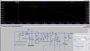
Rather than use an integrated regulator for the job, I am going to use 'what I have', so for kicks I just used spice to make a generic NPN pass linear regulator with an opamp. The opamp in the regulator has its own seperate power supply at 9v.

My first port of call for an opamp for so called 'DC applications' is the venerable LM358. But I fear this may be too slow to hold regulation.

Now, I could go on all day about the specifics, but really I just wish to know if anyone has made their own linear regulator for this sort of situation? as in, being capable of holding regulation when a sudden large step-change in load is applied. I realise there will always be *some* change in output voltage (nothing works instantly) but aside from adding a massive low ESR cap on the output, any tips?
 
Why not a shunt regulator? Just reminds me of a piece of equipment I used to work on with a 15 KV 1 Amp TUBE shunt regulator controlled by a transistor. The tube was the HV shunt.
 
Hello there,

When trying to regulate the output to such a high degree of accuracy for some time periods it gets hard to do because all of the parasitic elements enter into the picture. While normally ignored, going for great accuracy over short time periods means they actually become the most important circuit elements to consider.
One such element is the power supplies series inductance, and another its series resistance. Normally these are compensated for by the feedback, but the feedback can only work so fast, and even with extremely fast feedback then what becomes important is the amount of overhead voltage. Without enough overhead voltage the fast feedback doesnt matter because now the driver can not compensate for the series inductance in the power supply.
This usually means adding parallel capacitance to the output to help it hold up under intense, fast load application. The capacitance provides the needed current so that the output can get what it needs without having to negotiate the feedback and driver. Of course it must be low ESR to get this to work.

There are other problems that could come up too through with the addition of output capacitance. In short, the problem has to be specified just a little bit better. For some examples ("constant" means within 5 percent of initial output):
1. When we connect a 5uH inductor with 10m ohm series resistance to the output we want the output to stay constant at 2v for at least 10us.
2. When we connect a 5uH inductor with 20m ohm series resistance to the output we want the output to stay constant at 2v for at least 10us.
3. When we connect a 5uH inductor with 20m ohm series resistance to the output we want the output to stay constant at 10v for at least 15us.
4. When we connect a 5uH inductor with 10 to 20m ohm series resistance to the output we want the output to stay constant at 2v for at least 10us.
Just some examples to give you any idea how to spec this problem a little better.
 
Hey guys,

Roff, I'm planning on using a low RDSon N-channel MOSFET, low side. As it is in series with the inductor, it will develop a voltage of I*RDSon across it, I'm aiming for <30mOhm on resistance, and since the voltage is so low (2V across the inductor, + 5V for the flywheel diode kick) a 20-40V MOSFET with low on resistance (with a gate voltaeg of 9-12V) should be easy to find. I can give part numbers if people want to know.

A shunt regulator is something I skimmed over when looking for a solution, efficiency isn't paramount, because of the short pulse width, say 100uS, every 100mS. But I chose a standard 'active' linear regulator because I have a current sense resistor right after the voltage regulator, before the feedback to the opamp.
This is so the voltage across the inductor is held at 2V (minus the MOSFET Vdrop) and so I can use a higher value current sense resistor to minimise any offset errors in the crreunt sense amp. I have 5, 10,12,15,25mohm... but I chose a whopping 0.1ohm for 0.1v/amp. So... the although the regulators output is for 2V, it slowly increases this as current increases to compensate for the voltage drop across the resistor. I am unsure just how quickly shunt regulators can respond?

Mr Al.

You are completely correct! The reason I skimmed over some details was mianly to avoid another 'topic twist'. That is, to keep this on track for a 'fast linear regulator'. But yes, of course the purpose of the design is important as well, to provide a context.

I played around with LTspice, mainly because of my limited knowledge of 'poles and zeros' and phase margins involved in regulator design even after reading these great articles:
https://www.electro-tech-online.com/custompdfs/2011/04/AN-1148.pdf
**broken link removed**

Although it is generally best to start designs from 'ideal components' (as in, the fastest opamp, best caps etc..) I played around with trying parts I actually have, to see their limitations in the circuit. Changed the LM358 to a TS461. From 1MHz to 12MHz bandwidth, made a huge difference. The only thing I need to tweak is the capacitance and ESR of the output cap.
Too loo capacitance, and it droops too much. Too low ESR of the cap, and it creates some oscillation. This is not particularly based on theory :/ literally just trying combinations and keeping track of its result. I'll put up a schematic with its transcient response.

As for examples of 'narrowing down' its requirements. This is the tough bit. I shall be testing 'unknown' inductors, by providing 2V, and timing how long the current takes to reach 1A (actualluy its configuration between 50mA, and 6A). So, the 'on time' can vary between 2.4uS for a 4.7uH inductor, and perhaps up to 10mH, for a 20mH inductor. The voltage output of the regulator can also be set to 1V, with a 1A peak, this effectively makes (time in S) = (inductance in H).

So, the on-time can vary greatly. But also the current can. However, one thing that makes it 'slightly' easier is, because I'm testing inductors, the current ramps linearly, so it is not a sudden 'step change', although for low inductances, it can be quite steep :)

Heres my LTspice circuit, I haven't included the controller part, because that is just a mess of logic and comparators to emulate my AVR software :)

Am I going about this the right way? It looks deceptively simple to me, even if it is rather senstive to the outpu caps value and ESR.
 

Attachments

  • HighCurrentStep1.png
    HighCurrentStep1.png
    42.3 KB · Views: 211
Why are you shooting for such high currents? Are you trying to saturate the inductors' cores?
 
Why are you shooting for such high currents? Are you trying to saturate the inductors' cores?

Thats exactly what I am trying to do :)

Whilst it started as a way of measuring inductance in power ferrites (inductors, AND SMPS transformers) I thought, adding more current capability and I could also have a standalone circuit that can give me a 'rough' idea of saturation current. That would also allow me to measure the resistance of windings too to a certain degree. Effectively, making my own little test box for 'unknown' ferrite inductors/xformers, albeit with limitations on the two secondary measurements (Isat, and R).
So, I'm after fairly decent accuracy for inductance (5%?), and rough indications of R and Isat, so I don't have to set up my scope and use a high current supply every time I want to check something.

I have had problems measuring inductance using other methods, but I won't go into that here as it was covered in another thread.
 
Hello again,

I think you are doing very well with your spice circuit, however the model is missing something. The series inductance that would appear in series with the output and possibly in series with the capacitor after the pass transistor and possibly in series with the input caps before the transistor, and possibly between the power itself and the filter caps. At the very least, some small inductance on the output to simulate real life wiring.

The LM358 would never work for this app so it's a good idea that you went to a better op amp.

Also, the 'sense' lead (that going to the small resistor R10) is best done with a separate lead to the DUT, and same with the ground lead from the reference voltage V4. Those two leads would be brought out separately from the power leads so that they make contact with the actual DUT lead connection points. That means that the sense voltage is actually the voltage across the inductor and not the voltage across the output of the regulator. Since this might not work too well with the ground lead, you'll have to make sure that the ground lead to the ref voltage source V4 is connected directly to the common for the MOSFET. You'll have to compensate for the MOSFET losses too. If the inductor can be connected directly to the test set, the sense line might be ok connected to the very output terminal of the positive output lead. That way it makes up for some of the inductance in the circuit as well as resistance.

If there happens to be too much oscillation sometimes a small series resistance can dampen that out.

To make the response faster, sometimes derivative feedback is used. This technique falls under the general category of "state variable feedback". This kind of feedback makes predictions about the future output based on the slope of the output, and because of this it can provide additional feedback information to tell the circuit to drive the output harder than it normally would to help make up for the sloping output as you noted with a quick inductive connection. This would involve measuring the slope of the output and combining that with the normal feedback and adjusting the level so that it doesnt oscillate but does compensate somewhat for the normal slope. The result is less slope than without it. The derivation is mathematical, but unfortunately it requires a lot of exacting knowledge of the circuit components and in this case the little inductance here and there which is hard to nail down, so an adjustable network would probably be best so it can be fine tuned to fit the stray component values. You may not need this, but something to keep in mind.
 
Last edited:
Mr Al,

Just ot let you know, I have not forgotten about this project, or the help/advice you have provided. I know it can be frustrating when people ask questions about a project, it gathers momentum, then the OP suddenly disappears from the thread. I'm afraid its just work and general 'life' getting in the way. That said, I always keep notes/simulations/PCB files/schematics of all my half arsed idea's, and when time allows, revisit them, if not for necessity, then for closure :)

So, hopefully, I can knock up a few little test PCB's of the various 'modules', namely the main regulator, current measurement and inductor switch in the above LTspice schematic. Then it can be mounted on stripboard for the digital part to allow for easy modifcation (so the current paths and signals where parasitics are critical, are on a PCB with large wide traces and ground plane).

Interestingly, I revisited this thread by accident from a google search about some unknown inductors I've salvaged from various laptop motherboards and LCD tv power supplies, and came to the conclusion this was a worth while venture, if not just for me, then others who like to salvage and/or wind their own magnetics without having to do a mass of calculations first, and *then* using trail and error.

Thanks again Mr Al. Suggestions noted, and hopefully will assist in creating final design for the 'high current voltage regulator' part. Then I'll attempt to simplify it down tomake it easier for others to replicate - the digital side should be straightforward, an AVR/PIC, and some code - but analogue is not my strong point, and is arguably much more complicated.

Blueteeth
 
lol over two years later and I've revisited this project. This time with much more success in the method of measuring inductance, saturation, and DCR of an unknown inductor. However, the linear regulator is still giving me grief, because its output voltage is low (1 or 2v) it has to respond rather quickly to account for the voltage increase across a low side current sense resistor, and has to cope with peak currents of 7-10A (haven't decided the maximum yet).

To make matters more complicated, I decided to use the same opamp/transistor linear reg to regulate current - albeit not at the same time. It should be able to switch between current regulation, and voltage regulation, as these are two separate 'tests' its not a CC/CV supply, and there is plenty of time to switch between the two.

I have noticed with a relatively fast opamp (6-12Mhz GBW) and no compensation, it is actually stable when regulating voltage, and a very low ESR output cap (20mohm). However, as soon as I use the current in the negative input to regulate, with an inductive load on the output, it oscillates. It seems I must slow this down significantly to provide current regulation, but, such a network when used in voltage regulation would ruin its transient response (for testing a small inductor, it must hold regulation for 0-5A for around 3us).

I am toying with the idea of actually making two regulating opamps, using the same pass transistor, with diodes so each one can control the output, but I am struggling with an effective way to switch between current regulation, and voltage regulation.

A quick run down of what I want to acheieve:

A opamp/transistor based circuit, with a Vref input, a Iout signal (low side 0.1ohm current sense resistor, with fast opamp x10 gain), and I set, with Vout. Also, a logic line I can use to select between the two.
So, when the logc input is say... 1, the circuit regulates the voltage to whatever is on Vref (no gain, 1:1 ratio). This must have a fast transient response. Iout can then be used to see the current flowing to the load (which is an inductor, so it'll be a ramp)
But when the logic level is low, the circuit should regulate current, albe it quite a low current, between 50 and 200mA. I will then need a differential amp to measure the voltage across the load - or just subtract the current x sense resistor.

Note, as I said before, this isn't strictly a CC/CV supply, as there shouldn't be a current limit in voltage regulation mode, I'm just measuring. And these will not be used at the same time, just wanted to see if I can get away with using the same
opamp circuit and pass transistor(s) for it :D

That all seems complicated, so here's a schematic, thats worth a thousand words.

Current_reg1.png

Note, I found that putting the output cap (C1) across the load, rather than just the output to ground a lot more stable for sensible ESR's. In voltage regulation mode,
this voltage should remain the same anyway. R5 and C2 are my half hearted attempt to slow things down, without slowing it too much. In voltage regulation, the output of the curernt amp won't be used... instead a differential amp measuring the voltage across the DUT will be used. I'm kind of at a loss here...
 
Hello again,

It's been so long i am not entirely sure of what you are trying to do here.

Are you saying that you want to regulate the output voltage instead of current regulation, and want to be able to switch between these two modes, and use a differential amp on the output to measure the voltage and provide feedback? If so that probably isnt too hard to do, but you cant really regulate the DC voltage across a power inductor because the inductor response will only be a DC current which will be very large unless the DC voltage is very small. With 10 volts and 0.1 ohm series resistance in the inductor the current would be 100 amps for example. But maybe that's not what you want to do, so let me know.
 
Hi there!

Surprised someone answered, as so many 'old threads' that get resurrected can be a bit of a turn off.

Ok, you've pretty much understood exactly what I'm trying to design, amazing considering I'm not great at explaining things! So, I'm measuring inductors using a 'splat test'. Using a constant voltage, switching an inductor with a MOSFET across it, and measuring the ramp. I'm fairly certain I have the measurement part down (timing between two current thresholds). Because I want as much time as I can get to get the best resolution even with <4.7uH inductors, I'm using a low voltage, 1V or 2V, to slow down the ramping current. Also, simple values like this make for easier calculation. Once a certain current has been reached, the MOSFET will turn off, and for a 100uH induct, with 1V supply, and a threshold of say, 3A. That's 300uS. Larger inductors will be sensed with a timeout, and the current threshold lowered so that I'm not trying regulating the voltage when serious amperage flows, for any length of time.

Now, so far thats just a fairly simple 'voltage regulator'. Built with opamps and transistors to avoid off-the-shelf devices' current limit. I know there are 10A linear regulators out there, but I fear they either won't have the response times needed, or have special requirements.

The reason I want to be able to change this into current regulation is to measure the inductors resistance. This time, response time isn't needed, I'm putting a small current through both the inductor and the switch, and measuring the voltage across it.
This gives a small voltage drop (probably won't be able to get <10mOhm resolution though) and so, knowing the set current can work out the resistance of the inductor and MOSFET. Using a known resistor in place of the inductor, this can zero-out the MOSFET's resistance. Resistance is important because this affects the current ramp when measuring inductance, plus its also a handy thing to have on an L meter :)

I guess, my problem is, not actually designing a voltage regulator, or a current regulator, but finding a way of both being able to use the pass transistor, at different times. So far, all I am doing is changing the negative input of the regulators opamp from a measured voltage (differential amp and subtracts the current sense voltage from the regulators output voltage), to a voltage that represents the current. These require very different control loops, essentially fast and slow. I'm not really after speed when measuring inductor resistance, there will be some ringing, so I can just wait for this to settle before taking measurements, but the voltage regulation mode should be stable.

I'm venturing into bode plots here... somethign I do not fully understand but have many app notes to help me (and LTspice). But perhaps I could just use two different opamps? and switch between the two somehow? (current steering diodes maybe?).

Once again, I do tend to waffle, and whilst its not horrifically complicated, its not easy to explain clearly, so here is what I have so far. The previous schematic was a simple 'current regulator' using the low-side current sense setup I have. Very crude loop network to slow things down, but it works reasonably well in simulation. Here's the schematic of the main design, this time in 'voltage regulation mode'... with very little compensation:

Linear_reg2.png

Apologies its not pretty. I can't seem to make 'nice looking schems' on LTspice.
 
Hi,

You cant set up a switch to switch between the two modes? Or you want to do it digitally?
An analog switch comes to mind without thinking about this too much yet.
Sometimes you can set it up to do both, as long as the current mode can be adjusted high as that will keep the current mode from kicking in too soon when in voltage mode. In current mode you dont care if it tries to regulate voltage because the voltage will never get high enough to start to regulate anyway. That's the way most simultaneous voltage and current regulators work anyway. During the current mode, the voltage should be pretty darn low due to the series resistance of the inductor, but if it's not then just set the voltage regulation higher...assuming you can do that already somehow.
 
I've been close to being in your shoes, but somewhat different. I designed a 2 or 4-terminal I-V converter that had 4 ranges from +-100 mA FS to 0.1 mA FS for a +-10 V output. It was bias-able from -10 to +10 V. I had trouble driving capacitance loads. So, I could bias in the 10's of MV levels and maintain a voltage +- 1 mV at 100 mA.

You can consider this sort of an SMU or Source Measure Unit), but mine could stomach an AC input with an AC output. I was limited by the power supply and the driver. The power supply being +-15V and the driver being limited to like 200 mA.

You can think of a system as being either 2 modes simultaneously or a particular control mode with a compliance. So, in my design, the system could see the full supply voltage, but that could be minimized by using the 2-terminal mode first. I could have implemented a contact-check function too.
It was an atypical ZRA or Zero Resistance Ammeter with a higher range, That high current range and the low voltage range made things particularly difficult.

So, anyway, these SMU's can "1) Source I measure V or 2) Source V, measure I, or 3) Measure V and 4) Measure I, but I preferred for call mine a 44-terminal I-V converter with bias and suppression. Suppression was limited to +-50 mA in a single range and, if enabled, would reduce the available biasing to +-5V. An analog peak detector was also incorporated. I could only measure set V and measure I. If I externally wired it in a particular way, then it could also be a Zero Resistance Ammeter taking a few mV of a voltage drop when inserted into a circuit,
 
Hi, sorry for the late reply,

Hi,
You cant set up a switch to switch between the two modes? Or you want to do it digitally?
An analog switch comes to mind without thinking about this too much yet.
Sometimes you can set it up to do both, as long as the current mode can be adjusted high as that will keep the current mode from kicking in too soon when in voltage mode. In current mode you dont care if it tries to regulate voltage because the voltage will never get high enough to start to regulate anyway. That's the way most simultaneous voltage and current regulators work anyway. During the current mode, the voltage should be pretty darn low due to the series resistance of the inductor, but if it's not then just set the voltage regulation higher...assuming you can do that already somehow.

A switch (be it digital, or analogue, controlled by a microcontroller, ) would be a convenient way, however, the Vref and Iref (max voltage and max current) are set by a 12-bit DAC, so of course these can be set to maximum, or minimum in order to turn on/off each part of regulation. So yes, in this way a CC/CV supply would be fine. You rightly pointed out the issue of setting the voltage part 'low' during current regulation, because as I'll be testing power inductors (perhaps up to Irms > 8A) their resistance will be super low. Although I realize that a really fine resolution for resistance is not easy, say if an inductor has DCR of 12mOhms, a 12-bit DAC (Vref 4.096) would give an ideal resolution of 1mv. So a current of 1Amp through that inductor, would only give 12mV which is so tiny to set, even a rail-to-rail DAC would struggle to keep that close to the ground rail (although the DAC would be connected directly to an opamp's input, high impedance). Perhaps I could use a small signal mosfet to pull the input to the opamp pretty much down to ground, even when the DAC outputs '0'. A series 10k resistance from the DAC and a 2n7000 would nail that.


I considered using analogue switches to change both the input to the opamp feedback (a voltage representing output voltage, or output current) ... AND... switching the compensation. So I can have a very fast transient response for voltage regulation, and a slow one for current - to reduce ringing when switching in a relatively high value inductor. However, I'm cautious about inserting switches into feedback loops. If the output voltage goes up to max (say, 4V), I will not have much of a load on it without the inductor switched in.. so it will take a while to discharge the output cap.

As I was googling for ways to have 'separate control loops' controlling the same pass element, I came across this wonderful project:
**broken link removed**

He chose the second method, with one control loop, it seems he was after perfecting the transition between CV and CC - something which I do not need, as they will be completely separate tests. So the top schematic would be ideal. There are however differences between that and what I'm doing.

Firstly, He is using a MOSFET pass element, I'll be using a darlington (a high current, high gain main NPN, driven by a smaller NPN, Perhaps FZT1051A - 40v, 10A peak I, with a 2n222A).
**broken link removed**
So thats current driven, as opposed to voltage driven.

Secondly, he is using high-side current sensing. I looked into this, as it is generally preferential in all situations, (making load voltage measurements much easier) but had trouble deciding on a high-side monitor that was fast enough, as well as kept errors low even with small sense voltages (accurate at say 5A, but 20% error at 50mA). I have some MAX4172's somewhere, which dont' seem to be used as much as the MAX4173, but gain can be adjusted and appears to be fairly accurate. Only 800kHz bandwidth, at full scale range, which could be difficult for fast current ramps with low value (<4.7uH) inductors.
https://datasheets.maximintegrated.com/en/ds/MAX4172.pdf

I only have the LTspice model for the MAX4173T which seems both very accurate, and fast enough - that however, has double the bandwidth of the 4172.

I chose a low side measurement, because, despite the real hassle of using a differential amp to measure voltage across a load, it is straightforward, can be very accurate, and I can choose a high speed (>6MHz), very low offset opamp for it. I am unsure how to determine the maximum bandwidth I would need, for a given gain, to accurately keep track of the current ramp. worst case, say a 1uH inductor, at 1V, current sense resistor at 0.1Ohm. That will give an input ramp of 0- 0.1V, in 1us. Perhaps the maxim chips 800Khz (200Khz when input is low) would be fast enough?

But back to that first schem on the page:
**broken link removed**

The current amp uses a diode on the output to pull the voltage to the pass element low. Would this work with a NPN pass element? I perhaps I'm over thinking, but I can see the current regulation, overrides voltage. So if I set voltage to say 1V. And current to 0.2A, and put on a load with a low resistance to CC kicks in... the voltage regulator opamp would output as much current as it can, trying to bring the output voltage up - but the current opamp would pull that low via the diode. Seems like we're just shunting a few miliamps.

The second method he uses, despite his very cool use of compensation networks (and a brilliant explanation of them I might add) I fear would just be too slow to maintain output within 2% voltage with a sudden load ramp (not step) of say 5A within 5us.

Apologies for a very long, and somewhat boring post. But I think I'm missing something here, all the CV/CC supplies I have seen, use quite slow loops - and rightly so for bench supplies to keep things stable. Do you think the first circuit on that page is close to what I'm after?

Cheers!

Blueteeth
 
Hey KiSS,

Thought I'd do a separate post to reply to you.

I googled SMU's and thats pretty much exactly the sort of thing I am after. I am however, confused about how they are implemented, and couldn't find a schematic showing how they control either voltage or current - perhaps it really is a switched CV/CC regulator.

As for offsetting contact resistances, my meter will have a zeroing function, as well as a built in series inductor. This gives it a minimum inductance to measure (so things don't get hairy when measurements get to 0) as well as a way of zeroing out the MOSFET's resistance, inductors resistance, and contact resistance. I will indeed be using kelvin connections, albeit only to the output terminals, not completely separate as I don't plan on measuring inductors using leads longer than a a few cm. Any delays in measurements (say, response time of the current amp, comparators etc..) should be cancelled out because I'm not measuring things from 0, the difference between two points on a current ramp, both of these points should experience similar delays, which will be more or less cancelled out in subtraction.
 
Hi,

Im not sure i understand you here. When you have a power supply that does voltage and current regulation (sometimes abbreviated by CV/CC) if you set the voltage to max it will then be forced to current limit. If you set the current to max then it will be forced to voltage limit.

Are you sure you want to test chokes doing it this way? Maybe a square wave would be better. The DC part is then introduced as a DC offset in combination with having an idea what the series resistance is for the choke.
 
Excellent point.

There are a couple of reasons I chose to use a splat test for this as opposed to using frequency domain measurements.

Firstly, I have built several faily good LC meters. Of course these will not be as good as a precision bench unit, but I often measure flyback transformers (not the TV kind, just basic SMPS ones) and I have noticed that the inter-winding capacitance can skew measurements. When using a scope and pulse generator, the current ramp is often more accurate than using AC, also, because they are power inductors, the splat test is using the component in a situation it is designed to be used in, not a filter, but a power storage device. Another reason is.... maths. The LC meters often perform quite complicated floating point maths to calculate the inductance, whilst there are routines for this, it scares me. lol
Whilst LC meters can get very accurate inductance measurements, these don't often measure resistance, and one thing I do want to measure that I haven't seen these meters do is....

Saturation current. I'm trying to build a meter that is specific to power inductors/ferrite transformers. So I can wind my own, and get *some* information about the core, as well as measure unknown inductors/transformers liberated from various scrap electronics. Using a meter for L, a constant current supply and a volt meter for DCR, and a pulse generator and oscilloscope for checking saturation current seems like a lot of work just to get three parameters from one component. So I decided to try and merge these into one unit - without having to use an oscilloscope. Accuracy of course won't be as good as seeing saturation on a good scope, but to have all three tests in one small unit I feel would be extremely handy for amateurs and professionals alike.

It started as just a way of measuring saturation current. By applying a current pulse, and measuring the time between two current levels, then varying these current levels. Effectively sampling a ramp to check its gradient, once this gradient starts to increase - its getting into saturation, and since I know the current thresholds set, we can get a fairly good idea of the current saturation starts. The problem however, is in order to see where the current ramp starts to increase in gradient, we need to know the normal gradient when not saturating - that is of course a function of voltage and inductance. So really it has to measure inductance as well, and using this method, the inductors resistance has to be taken into account, giving our third measurement.

As many datasheets spec saturation current as a 'drop in inductance by 10%', that would mean as I measure the ramp, I'm looking for a time between current thresholds to drop to 10% of previous averaged values.

So, what started as measuring one thing, meant I had to measure 3, and I might as well display these giving a pretty good idea of the specs of a part. Its just a glorified way of doing this test: https://www.dos4ever.com/flyback/flyback.html#ind2 without requiring a scope. And frankly I believe its possible to get good results, but haven't seen any affordable meters to perform such tests. The idea is surprisingly simple, at least in terms of what the microcontroller will do, the devil is in the hardware. And various simulations in LTspice has given me confidence it can be done, without complicated calculations or super fast ADC's

So yes, its not the best way to measure inductance, but given it provides saturation current as well.. woudl be nice to have a small box, battery powered (high current pulses come from a cap bank) where one would attach an unknown inductor, or a few turns wound on an unknown core, and get some specs from it, without having take the artisan approach, setting up a messy test, and sorting my scope out :D
 
Hello again,

The test with a square wave is strictly speaking not an AC test. It's still produces a current ramp, it just repeats over and over which gives you time to make repeated measurements which would be sync'd to the square wave start.
The square wave voltage produces a ramp up and a ramp down, that's all. So you get two ramps that repeat over and over again. It's not hard to do at all.
This also gives you the option of taking the core through the entire BH curve, something you can not do with a single burst test.

Does this sound good or do you not like the idea of a repeating ramp for some reason?
 
Status
Not open for further replies.

Latest threads

New Articles From Microcontroller Tips

Back
Top