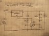
So I found this circuit after months of searching online. The output only powers a 6V bulb though. Can someone tell me how I can make this power 12V? Is there some sort of relay circuit out there that I could hook this up to and still make it dim?
here is the link to the circuit- https://www.chemical-ecology.net/papers/aesa83.htm
I need this circuit to somehow have an output of 12V (a little less would be alright) and be able to control 8amps. This will be running a total of 33 lights in series of 3's with 11 parallels. The specs of the light are forward voltage of 3.4 at 700mA.
If this is not possible to do or I am going in the wrong direction please let me so I can stop trying to make this happen.
Thanks
")