psychogenic
New Member
Greetings all,
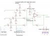
I'm attempting to create a summing amplifier using a single-supply op-amp. I've created and attached a schematic to describe where I'm at, and would like some input.
In order to avoid clipping and keep the sum of the incoming sine wave signals nice, I'm floating the inputs over VCC/2, then summing everything. I used a simple voltage divider to get the VCC/2 reference on the non-inverting input.
My questions are:
* it seems to work... any reason or conditions under which it wouldn't?
* is there a better way to achieve this, perhaps with a reduced parts count?
* are there any "gotchas" to look out for, in terms of impedance matching or somesuch--e.g. should the voltage dividers have resistors with much greater values, lower... does it matter?
Thanks in advance for your help--don't hesitate to ask if you need more info")
I'm attempting to create a summing amplifier using a single-supply op-amp. I've created and attached a schematic to describe where I'm at, and would like some input.
In order to avoid clipping and keep the sum of the incoming sine wave signals nice, I'm floating the inputs over VCC/2, then summing everything. I used a simple voltage divider to get the VCC/2 reference on the non-inverting input.
My questions are:
* it seems to work... any reason or conditions under which it wouldn't?
* is there a better way to achieve this, perhaps with a reduced parts count?
* are there any "gotchas" to look out for, in terms of impedance matching or somesuch--e.g. should the voltage dividers have resistors with much greater values, lower... does it matter?
Thanks in advance for your help--don't hesitate to ask if you need more info