Continue to Site

Welcome to our site!

Electro Tech is an online community (with over 170,000 members) who enjoy talking about and building electronic circuits, projects and gadgets. To participate you need to register. Registration is free. Click here to register now.

  • Welcome to our site! Electro Tech is an online community (with over 170,000 members) who enjoy talking about and building electronic circuits, projects and gadgets. To participate you need to register. Registration is free. Click here to register now.

Suggest a good opamp and schematic?

Status
Not open for further replies.

antknee

New Member
Hi,

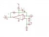
I want to drive a piezo from a signal generator via an opamp. So the config would be

Signal generator ---> opamp ---> piezo

I'd like the voltage multiplied by 10 from +/- 2.5V to +/- 25V
The frequency I need is up to 200KHz so a bandwidth gain product of 2MHz.
I'd like an output current of 100mA but I think at most I'll get is 50mA, is that right?
The piezo has an impedance of 100ohms, capacitance of 2nF, and frequency 130KHz. As it is a capacitive load I'll need to protect the opamp. The signal generator has an output impedance of 50ohms.

I'm a novice at electronics, so does this sound credible?

If so could you suggest a good opamp and point me towards a schematic that would get me started?

Thanks,

Antknee.
 
**broken link removed**. Use the parametric search to find one with the voltage, and gain bandwidth. LF156 might work.
 
Try this:

This is a common '741 OP Amp like a LM741. Pin 3 sets your bias. The resistors are usually 50/50 like two 47K resistors. I just clipped this out of an old schematic where I needed the bias to be closer to saturation. The resistor labeled R93 is your feedback gain or just gain. I've seen resistor values as high as 1Meg which gives maximum voltage gain but loss of drive power (less current).
 

Attachments

  • OPAMP-Amp..jpg
    OPAMP-Amp..jpg
    18 KB · Views: 222
A lousy old 741 opamp has a max gain of only 4 at 200kHz and a max output of only 1.5V p-p.
 

Attachments

  • uA741 opamp..PNG
    uA741 opamp..PNG
    33.6 KB · Views: 192
A lousy old 741 opamp has a max gain of only 4 at 200kHz and a max output of only 1.5V p-p.

Yeah but Audio,

I'm just giving him a starting point. Go ahead. Your the guru. Give him a better one. I just picked that one out of an old schematic and they are very common. I'm pretty sure you can still go down to the local RadioShack and pick one up if they are around. RadioShack is slowly disappearing in my neck of the woods. Well, another subject for another time. Just trying to give him something to work with :D
 
Hi,

Thanks for the link to the comparison website. It is pretty good, I will run through a number of specs and see what it comes back with. I will also get a datasheet for the LF156.

I am still reading up on the theory of opamps. Being a novice at electronics doesn't help. I have gotten a basic MCP6281 to light up an LED based on the input of the signal generator. And I now understand the basic purpose of inverting and non inverting schematics.

The term bias and feedback crop up a lot in electronics. Is there a simple explanation of the terms? Wikipedia gave me an insight into setting opamp gain with resistors, its explanation of feedback and bias seemed a little complicated though!

Thanks,

Antknee.

Though an OP Amp is many transistors, in the the case of "Bias" you will think of it as a single transistor. The bias will establish where on the load line the DC level will be set. If it is set to more positive than as your AC (audio or what have you) swings positive it may "saturate" which is sort of a squashing down of the positive peaks of the AC signal. This is what is known as "non-linear distortion" and can be heard in a speaker output if you are amplifying audio. The signal will not be very clean. If the bias is set more negative then the negative portion of you signal can be "cut off". Cut off simply means the transistor is switched off and therefore has no output. You can bias to extremes where your whole signal both positive and negative swing can saturate or be cut off. In the case of an Op Amp it is pretty standard practice to use a "voltage divider bias" with both resistors being the same value which will split the power supply voltage in half thereby fixing your bias dead center which is known as the Q point or quiescent point. This allows for the same amount swing both positive and negative at the input. So if you do not over drive the input, you will have a very linear (non distorted) output. This is known as "class A" amplification and is least efficient but gives a good high quality output.

Just a quick rough over view of biasing the control gate, base, etc of semi-conductors and tubes which would be called the "control grid".
 
This is known as "class A" amplification.

No.
Opamps use class-AB biasing because class-A biasing causes both output transistors to conduct their max current all the time and get too hot. In class-AB both transistors conduct a very small current at idle. Then only one transistor conducts for the positive-going swing and the other transistor conducts for the negative-going swing.

Biasing the output voltage at half the supply voltage allows the output to swing the most before clipping distortion.

I gave up arguing with the Audioguru ^^^^^ but I was close. Yeah they have the current mirrors and the other thing where it is sort of a push-pull, I can't remember the name. Synchronis amplifiers? Can't think of it but I see your point where they would be offset somewhat to allow for the slack of the two side to produce one output. Is it "complimentary"? Yeah I think that's what they call it. Complimentary amplifiers.
 
Complementary, in fact.
 
The bias will establish where on the load line the DC level will be set.

Ah that is it. It is easy to understand when put clearly. Thanks!

The opamp comparison website is telling me to use the LM3886. I recently downgraded from this chip because it is very complicated and I couldn't get it working properly, it wanted a pcb layout and I had all sorts of grounding and feedback problems, I intend to try again, but thought I ought to learn a thing or two about simpler opamps first. Will have to change specs again for the website.

Regards,

Antknee.
 
No.
Opamps use class-AB biasing because class-A biasing causes both output transistors to conduct their max current all the time and get too hot. In class-AB both transistors conduct a very small current at idle. Then only one transistor conducts for the positive-going swing and the other transistor conducts for the negative-going swing.
No.

There are op-amps which have a class-A output, I suggest you read the datasheets for the CA3080, CA3130, CA3160 etc.
 
I got the supply current and output current mixed up. There is probably a reason why its not called input and output current, but I have enough to learn already without worrying about that!
 
I got the supply current and output current mixed up. There is probably a reason why its not called input and output current, but I have enough to learn already without worrying about that!

The input is the input pin, not the power supply pin. They are completely different.
The input pin on some opamps needs a current. The input current is extremely small.

The output of an opamp can supply maybe 25mA max for most opamps.
 
I received an E-mail notice of a reply here where Hero says some old opamps are class-A.
Then he deleted his reply before this answer.
No they aren't.
 
They got a 68 watt Op Amp! Damn! I need to look that one up.
It is not an opamp. It is an excellent audio amp IC. Digikey has 483 of them today for $7.30US each.

A guy in New York makes a stereo amplifier with two of them and sells many for $4000.00 US.
I made and sold many before my Japanese women (and kid) workers left to assemble bogus TV satellite receiver boxes instead.
The excellent audio amplifiers are called "gain clones", look in Google.

Wow! That sounds like a pretty awesome deal. So this guy uses the 68 watt IC's as the finals? How does he get so much money for his stereo? Just off the specs or what?
 
Status
Not open for further replies.

Latest threads

New Articles From Microcontroller Tips

Back
Top