Electro Tech is an online community (with over 170,000 members) who enjoy talking about and building electronic circuits, projects and gadgets. To participate you need to register. Registration is free. Click here to register now.
Welcome to our site! Electro Tech is an online community (with over 170,000 members) who enjoy talking about and building electronic circuits, projects and gadgets. To participate you need to register. Registration is free. Click here to register now.
A two-way crossover network divides the frequencies for a tweeter and a woofer, not for a sub-woofer.
A three-way crossover network divides the frequencies for a tweeter, a midrange and a woofer. Also not for a subwoofer.
A crossover for a subwoofer is an active circuit that divides the line level signal frequencies so that very low frequencies go to the subwoofer's amplifier and the other frequencies go to the other speakers' amplifiers.
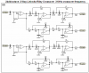
This circuit is an excellent active crossover. The opamps can be TL072 dual and TL074 quad. They need a dual polarity supply for this circuit.
For a crossover frequency of 102Hz then replace the 33nF capacitors with 100nF and replace the 66nF capacitors with 200nF (two 100nF in parallel).
This circuit is an excellent active crossover. The opamps can be TL072 dual and TL074 quad. They need a dual polarity supply for this circuit.
For a crossover frequency of 102Hz then replace the 33nF capacitors with 100nF and replace the 66nF capacitors with 200nF (two 100nF in parallel).
Hello. Could you tell me how to convert this circuit so that I could use this circuit with a single polarity supply ?or If you have any sub woofer circuit that uses single polarity supply so could you share with me the schematic ?
Thanks !
For a single supply voltage you need to add an opamp that makes a "phantom ground" voltage of half the supply voltage. then all the parts that bias the opamps must connect to its output instead of to ground.
I showed the circuit for an excellent 2-way active crossover.
The circuit for a 2-way passive crossover network depends on the spec's of the woofer and the tweeter.
Some excellent speakers just use a capacitor to make a simple highpass filter for the tweeter and an inductor to make a simple lowpass filter for the woofer. But other tweeters are too fragile and need a shraper cutoff. Also other woofers have a bad resonance at about 5kHz that needs to be attenuated.
The speaker manufacturer should have recommended crossover circuits for their speakers.
This site uses cookies to help personalise content, tailor your experience and to keep you logged in if you register.
By continuing to use this site, you are consenting to our use of cookies.