Ok, so I'm a noob!
Firstly, on basic electronic project circuits, when I see (eg) +9v and an earth symbol on the sircuit, do I connect a nine volt cell positive end to the +9v connection, and the negative end of the cell to the earth?
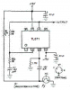
Also, what do I do on the attached circuit, do I run 2 9v's in parallel, +9v to the positive end of the battery, -9v to the negative end, and earth to the join between the two cells?
Cheers!
PS. Copyright not owned by me for this circuit: Fair use, limited resolution screenshot for education.
And above the photo transistor the diagram reads "NC" I assume that means don't connect that connection to anything?
Firstly, on basic electronic project circuits, when I see (eg) +9v and an earth symbol on the sircuit, do I connect a nine volt cell positive end to the +9v connection, and the negative end of the cell to the earth?
Also, what do I do on the attached circuit, do I run 2 9v's in parallel, +9v to the positive end of the battery, -9v to the negative end, and earth to the join between the two cells?
Cheers!
PS. Copyright not owned by me for this circuit: Fair use, limited resolution screenshot for education.
And above the photo transistor the diagram reads "NC" I assume that means don't connect that connection to anything?
Attachments
Last edited: