Continue to Site

Welcome to our site!

Electro Tech is an online community (with over 170,000 members) who enjoy talking about and building electronic circuits, projects and gadgets. To participate you need to register. Registration is free. Click here to register now.

  • Welcome to our site! Electro Tech is an online community (with over 170,000 members) who enjoy talking about and building electronic circuits, projects and gadgets. To participate you need to register. Registration is free. Click here to register now.

Stumped novice needs advice

Status
Not open for further replies.
Dear All

How to increase the voltage/current output from a flip-flop.

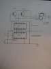
I’m using a large 7-segment common anode LED driven from a 7447 decoder/driver. The LED has 2 anodes which are used to switch the LED from red to green with a SPDT switch.

I want to replace the SPDT switch with a push-to-make button (for reasons that seemed good at the time) so I put in a 7453 J-K flip-flop (with a 7414 to debounce the mechanical button) and connected the Q and NOT Q outputs to the anodes of the display. This works fine with Q and NOT Q toggling the LED from red to green every time the button is pressed.

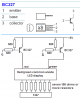
The problem is that there is not enough current from the flip-flop to drive the LED to required brightness even if I leave out current limiting resistors. I tried a switching transistor but the increase was minimal.

Can anyone advise if there’s a way around this? Sorry if I’ve been long-winded.

Thanks in advance.

Trevor
 
Trevor,
A simple solution is to use 2 NPN transistors connected as emitter followers.

Connect the base of one to Q and the base of the other to Qbar. The collectors are connected to Vcc.

Connect a resistor from each emitter to the respective LED anodes (ie. 2 resistors).

When Q goes high, its transistor is turned on and (say) the red LEDs light.

When Q goes low, the other transistor is turned on since Qbar goes high and the greens light.

Len
 
Len

Many thanks for the reply. Unfortunately, that is one of the things I've already tried but without any noticeable improvement - even if I leave out the resistors.

Actually, it's just the green that's too dim. The red is fine, even driven directly from the flip-flop, which led me to suspect that the LED itself was stuffed but I have half a dozen and they all behave the same way. I tested them on a bench power supply. Also, I can see the same difference with single LEDs too - for any given voltage, the green isn't as bright as the red.

I must be doing something wrong or missing something but haven't been able to nail it yet.

Thanks again

Trevor


ljcox said:
Trevor,
A simple solution is to use 2 NPN transistors connected as emitter followers.

Connect the base of one to Q and the base of the other to Qbar. The collectors are connected to Vcc.

Connect a resistor from each emitter to the respective LED anodes (ie. 2 resistors).

When Q goes high, its transistor is turned on and (say) the red LEDs light.

When Q goes low, the other transistor is turned on since Qbar goes high and the greens light.

Len
 
By using a correctly connected driver transistor, and suitable current limiting resistor, you can make it as bright as you wish (within the specification of the LED).

If it didn't work?, then you've probably done something wrong?.

Try posting your circuit for us to look at!.
 
Nigel, thanks for the reply.

You're probably right but I've checked and can't see the problem unless it's the design itself. Anyway, I've (I hope) attached a jpg of the circuit so would be very grateful if you could take a look. Sorry for the poor quality.

Vcc is supplied from a 1A 7805 regulator.

Thanks again

Trevor

PS Sorry, I just realised there's a big mistake in the drawing. I've got the collectors wired to GND instead of Vcc. I'm getting old! I had them correct on the breadboard! I'll try and update it.


Nigel Goodwin said:
By using a correctly connected driver transistor, and suitable current limiting resistor, you can make it as bright as you wish (within the specification of the LED).

If it didn't work?, then you've probably done something wrong?.

Try posting your circuit for us to look at!.
 

Attachments

  • flip-flop_199.jpg
    flip-flop_199.jpg
    113.6 KB · Views: 992
Old TTL logic ICs aren't designed to source much voltage or current when high. Maybe only 3V at a couple of milliamps. When an LED load tries to draw 10mA or more then the output of the logic IC sags. Your green LED probably needs about 3V at 10mA or more.
Use Cmos logic which swings the full supply voltage. It can drive an emitter-follower for more current very well.

If you insist on using old TTL logic, it can drive common anode LED displays fairly well. A 74xx IC can sink to ground 16mA. :lol:
 
Many thanks for the advice. Would using CMOS be simply a case of
looking for equivalents for the existing TTLs and are they likely to be pin compatible or would this require a re-design of the circuit?

Regards

Trevor


audioguru said:
Old TTL logic ICs aren't designed to source much voltage or current when high. Maybe only 3V at a couple of milliamps. When an LED load tries to draw 10mA or more then the output of the logic IC sags. Your green LED probably needs about 3V at 10mA or more.
Use Cmos logic which swings the full supply voltage. It can drive an emitter-follower for more current very well.

If you insist on using old TTL logic, it can drive common anode LED displays fairly well. A 74xx IC can sink to ground 16mA. :lol:
 
Hi Trevor,
I just realised that you are switching the colour of an entire 7-segment display, not just a 2-colour LED.
Then your existing TTL ICs can drive a PNP transistor for a high output voltage and current for the display.
 

Attachments

  • bc327.png
    bc327.png
    10.4 KB · Views: 975
Yes, Audio's circuit should work very well.

I had assumed (I should learn to read) that you were using CMOS.

Len
 
Hi Len,
The last TTL circuit I built was in about 1975, then I fiddled with 74LSxx for 2 years before discovering Cmos. How about you?
 
G'day Audio,
The last time I worked with TTL was in 1969 at a research lab.

CMOS is much easier.

Len
 
Hi All

Many thanks for all the help and circuit suggestions. I'll post the results when I have tried it out. I guess TTL is out of date, huh? I should get to grips with CMOS. I think all my circuit cookbooks date from the 70's!

Trevor
 
Audioguru, many thanks for this. I'll try it out and post the result. By the way, an I ask you how you produced the drawing? Did you use a dedicated schematic drawing package?

Thanks again.


Trevor


audioguru said:
Hi Trevor,
I just realised that you are switching the colour of an entire 7-segment display, not just a 2-colour LED.
Then your existing TTL ICs can drive a PNP transistor for a high output voltage and current for the display.
 
Hi Trevor,
My "Cmos Cookbook", by Don Lancaster was 1st printed in 1977 when I discovered Cmos. I have worn out many of these books and my latest copy was printed in 1992. There might be a newer revision now.

I do all my schematics and modifications of schematics from other people by using Microsoft Paint (Windows XP Home, sevice pack 2).
In the one for you I just copied and pasted from the transistor's datasheet and held down the shift key to make straight lines. I was too lazy to copy and paste the proper symbol for resistors so I just used rectangles. :lol:
 
I just opened Power Point for the very 1st time. I don't have a clue how to begin drawing anything. I was hoping a wizard or something would popup and assist me. :lol:
 
I found the paperclip under the help button! Thanks. :lol:
It asked me what I wanted to do. I typed what I wanted and it answered, "huh?"
I think the paperclip has more to learn than me.
 
Hi Audioguru

I tried out your circuit suggestions and got the circuit working but the transistors only switch if I increase the external supply voltage from 12 to 14 volts.

I should explain that the on-board power supply is a 7805 regulator together with a couple of caps for smoothing. I'm powering it from a 3A bench power supply set to 12 volts (the circuit will eventually be run off a 12v dc motorcycle battery) and the measured output after the regulator is about 4.8volts.

Should I try reducing the 680 Ohm resistor between Q and transistor base to address this? I'll carry on fiddling around in the meantime.

Many thanks again for the help.

Trevor


audioguru said:
Hi Trevor,
I just realised that you are switching the colour of an entire 7-segment display, not just a 2-colour LED.
Then your existing TTL ICs can drive a PNP transistor for a high output voltage and current for the display.
 
Hi Trevor,
The circuit should work fine with your 4.8V supply. Anything more than 7V will exceed the absolute max voltage rating of the 74LS73.

When the output of the 74LS73 goes low to 0.5V or less. the base of the transistor will be pulled down to about 4.0V. The 680 series resistor will have at least 5.2mA through it and the transistor's base will get at least 4mA. With each segment of the display very bright at 30mA, seven of them draw 210mA. Therefore the transistor must have a current gain of 210/4 = 53. Its guaranteed minimum is about 60.

Typically, a BC327 will saturate at 0.25V with a 210mA load and 4mA of base current.
Maybe you have its emitter and collector pins reversed.
Maybe you have a weak BC327 transistor. General Semi sell them in batches of selected current gains and their BC327-40 has lots of gain. :lol:
 
Status
Not open for further replies.

New Articles From Microcontroller Tips

Back
Top