Continue to Site

Welcome to our site!

Electro Tech is an online community (with over 170,000 members) who enjoy talking about and building electronic circuits, projects and gadgets. To participate you need to register. Registration is free. Click here to register now.

  • Welcome to our site! Electro Tech is an online community (with over 170,000 members) who enjoy talking about and building electronic circuits, projects and gadgets. To participate you need to register. Registration is free. Click here to register now.

strobe light

Status
Not open for further replies.

jrz126

Active Member
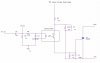
I finally got my strobe light working properly. I was wondering, what determines the amount of light output of a strobe? The energy or the power?
I think it's the power, here's my reasoning:
I found a great site that explained some of the calculations.
To find the energy it's 0.5*C*V^2, which I calculated to be about 1.36 something Joules.
Then to find the power disipation, it's flash rate * Energy.

Now when I first built it I had my flash rate set at about 1 Hz, and it wasnt very bright at all. (power disipated is 1.36 W)

I then changed it to about 15 Hz and it was really bright. (power ~= 20W)
My strobe is rated for 24Watts.

Now if this is correct, could I lower my capacitance so that I can safely increase my flash rate?

Hope this makes sense, I've got some homework due in about 20 minutes and I wanted to get this post in.
 
The energy per flash should be the same, although at high flash rates the capacitors may not have time to recharge fully, in which case the energy per flash will be less.

By having a high flash rate it's not any 'brighter', just that you have more flashes in a shorter time.

The whole point of a strobe is to flash at a certain rate, often intended to 'freeze' a moving object, I don't see much reason for wanting to try and produce the fastest flash rate you can?.

There are certain restrictions on how fast you can make it flash, not the least of which is that the tube is only rated for a relatively small number of flashes before needing replacement.
 
I dont really want to increase the flash rate, I was just wondering if my thinking was correct.

here's another question: Will I get more flashes out of a tube if I run it at less power? Say I run 1 tube at 10Hz and 20W, then I run another tube also at 10Hz but at 10W. Will the second one last longer?
 
i could use a strobe to see the performance of my propellers , what did you use for T1, the transformer..?

very cool roof LEDs btw ..
 
here's the schematic that I used:
https://www.aaroncake.net/circuits/strobe2.htm

and I also used this schematic to replace the voltage doubler in the above schematic. thanks to pommie for that.

electronics goldmine has all the parts needed
www.goldmine-elec.com

Here's another page with alot of info **broken link removed**

and thanks for the compliment...it was alot of work but it's well worth it.
 
thanks, i have a flash tube , but i also have a flash unit from a camera..
i wonder wether i could modify that..
this question is for anyone..
i once stuck a neon bulb in a socket , it made a popping sound and sparked and blew a circuit breaker, why??
i allways thought that they were connected to mains power??
although i didnt get a shock cuz i was only touching the glass bulb part, i was really surprized , that it didnt just light up..??
 
Hi Willi,
I did that too with a neon bulb without a current-limiting resistor, mine blew-up and disappeared. Luckily I still have my fingers and vision.

Neon bulbs always have a current-limiting resistor. They have a voltage regulator effect like a zener diode or LED. Have you ever tried it with them?

As the voltage of the AC mains sine-wave increases, also does the current until a certain current is reached when the neon bulb arcs, dropping the voltage drop and increasing the current without limit.
 

Attachments

  • neon_lamp_spec_s_885.gif
    neon_lamp_spec_s_885.gif
    13.1 KB · Views: 1,063
mine didnt blow up, guess i was lucky..but it did end up with a tiny blob of melted lead on each leg..for 120V what current values should i try for ?
and should i connect it across the mains?or maybe one lead to ground?
 
Lots of good data on xenon flashtubes:
https://members.misty.com/don/donflash.html

The energy of a cap, in joules, determines the intensity. Note that not all the cap's energy will be used, it does not drain to 0v. There are some differences in how the tube discharges between a lower voltage, higher capacitance cap and a higher voltage, lower capacitance cap even when the joules consumed is the same. Consult the tube's datasheet on the appropriate voltage.

The tube also has a max wattage, wattage is joules per second so if you know joules per flash and flashes per sec this is easy to calc. Exceed it and the tube can overheat. There is also a max joules per flash, exceed this too far and the tube may even crack from the thermal & pressure shock.

The display is not entirely linear; if you run it at 25% of its joule rating, you may get less substantially less than 25% of its light. So you may just want a smaller tube. Some tubes are just not designed for high flash rates from a bunch of low joule flashes.
 
Hi Willi,
With 120VAC a low brightness NE-2 neon bulb uses a 220K series resistor for 25K hours life. A high brightness NE-2H bulb uses a 30K series resistor for the same life.
It is difficult to calculate their current because they are off for each half-cycle until the voltage rises to their striking voltage of 65V to 90V.
 
needless to say , i am a little leary to try again, what would happen if i just connected the hot through the neon to resistor to ground..?
 
Same thing as wiring the hot to the resistor then the neon bulb to ground (neutral). Either way, the resistor limits the current to the neon's design value of about 1mA.
Without the resistor you'll have many Amps of current, maybe 20,000 times too much!
 
I'm working on making it so that I can control my strobe with a 555 timer. this is the schematic I'm going to use for the optoisolation.
What kind of voltage rating do I need on my optoisolator?
 

Attachments

  • opto_203.jpg
    opto_203.jpg
    49 KB · Views: 987
i found a usable strobe ..i had one the whole time.. :roll:
my timing light ..
i hooked up one of my armatures that would fit, into where the spark plug wire goes , and hooked it to a small battery , and it works !!
now all i need to do is hook the armature to a relay and it should work great... :wink:
jeff , i dont see a schematic..
 
hmmm....the forum gnomes must have done something with it, or I forgot to put the link in there...
**broken link removed**

There you go...
 
this is sooo cool ..i got it hooked to a relay , actually i probably should just use a N channel fet, but anyway the timing is controlled by a 5Mhz oscillator divided way down.. till the propellers are look as though they are just creeping forward.. i suppose a varible trigger is in order here..
 
Strobe circuit

HI all!!

I have a couple of the Tiny cheap camera tube with 13 mm. arc length / BGA 0013.

I would like to build a cuircuit that can do the same as in the attached pic, and it must run of 12V, like a car battery.

I want to conntect it to my car alarm to really get some attention to it!!

Can you please help!!!
 

Attachments

  • JSPS0240-DOUBLE.gif
    JSPS0240-DOUBLE.gif
    172.8 KB · Views: 196
Status
Not open for further replies.

New Articles From Microcontroller Tips

Back
Top