lloydi12345
Member
I tried a simple flashing LEDs program on a breadboard and it worked well even if the two vcc and gnd aren't hooked together with the other vcc and gnd pin of the PIC.
Breadboard connections:
pin 1 - 10k ohms to Vcc
pin 13 & 14 - 4mhz xt osc
pin 32 - vcc
pin 31 - gnd
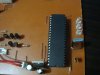
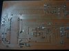
I already designed alot of PCBs and this is my first time to encounter this problem. Flashing LEDs on my newly designed PCB isn't working. What's strange is that, when I touch pin 13 of the PIC or even the copper path going to it makes the PIC work properly, but when I'm not touching it by my finger, the PIC wont make the LEDs flash.
PCB connections:
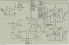
pin 1 - 10k ohms to Vcc
pin 13 & 14 - 4mhz xt osc
pin 32 - vcc
pin 31 - gnd
Can you help me?
EDIT: I tried desoldering the 4mhz XT Osc from the PCB and made a touch of my finger on pin 13, the LEDs go flash.
Breadboard connections:
pin 1 - 10k ohms to Vcc
pin 13 & 14 - 4mhz xt osc
pin 32 - vcc
pin 31 - gnd
I already designed alot of PCBs and this is my first time to encounter this problem. Flashing LEDs on my newly designed PCB isn't working. What's strange is that, when I touch pin 13 of the PIC or even the copper path going to it makes the PIC work properly, but when I'm not touching it by my finger, the PIC wont make the LEDs flash.
PCB connections:
pin 1 - 10k ohms to Vcc
pin 13 & 14 - 4mhz xt osc
pin 32 - vcc
pin 31 - gnd
Can you help me?
EDIT: I tried desoldering the 4mhz XT Osc from the PCB and made a touch of my finger on pin 13, the LEDs go flash.
Last edited:
 Oh, I've changed the code already.. Too bad I can't make the PCB work since the solder part now is messed up because of troubleshooting alot, so I'm abandoning my design and work for a new PCB design. Thanks though for the help really.