Continue to Site

Welcome to our site!

Electro Tech is an online community (with over 170,000 members) who enjoy talking about and building electronic circuits, projects and gadgets. To participate you need to register. Registration is free. Click here to register now.

  • Welcome to our site! Electro Tech is an online community (with over 170,000 members) who enjoy talking about and building electronic circuits, projects and gadgets. To participate you need to register. Registration is free. Click here to register now.

Strange behavior of LM317

Status
Not open for further replies.

futurewave

New Member
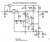
I used one of the suggested circuit in LM317 data sheet from national semi (page 8), in order to build up a (2-30V 3A) power supply. Due to lack of some components in my location I changed the current amplifier transistor MJ4502 to MJ2955 and also LM301 op amp to (NE5532 or TL071).

The transformer is rated for 24V AC 3A and I got a wide voltage range (1.25-32V DC) with this circuit. the problem is, while the load current increases the output voltage will increase a little too for example at 13 V DC with different loads the result is something like this:

100 ohm load --> 13.03 v
33 ohm load --> 14.15 !
15 ohm load --> 15.32 !!

I think the output voltage must be constant, and there must be something wrong with this regulation.
Any Idea about this ?
 

Attachments

  • Clip_2.jpg
    Clip_2.jpg
    36 KB · Views: 1,606
Pin 8 on an LM301 opamp has a completely different function than pin 8 on any other opamp. You used a different opamp so of course the circuit operates oddly.
 
Is C6 (16uf) of good quality? I'm thinking something is bad in the feedback reference circuit.


C6 is a Fuji electrolyte cap in my prototype I changed it to 10,16 and 33uf but nothing happened, I don't think the quality of this capacitor causes such a big drift in this circuit.


Pin 8 on an LM301 opamp has a completely different function than pin 8 on any other opamp...

Yes pin8 stands for compensation in lm301, I don't undrestand what is the function of pin8 while pin1 is labeled for Balance/Comp1 and pin 5 is Balance. Im tring to buy this IC and see the result with original component. it would be helpful to know more about LM301 if someone has experiences before.
 
Compensation capacitors aren't required for modern op-amps.
 
Finally I got LM301 and replaced it in my circuit in addition to D2 and C4 on PIN 8. Now the circuit is a clone of the original but the problem still exists! and I can measure a noticeable amount of voltage drift in this regulator circuit. I wonder how data sheet represents it as a constant Voltage/Current regulator.
 
Perhaps your 317 is bad. Have you tried another one?
How have you put the circuit together?
Solder? Breadboard? PCB? Maybe you have a bad connection.
 
I have tried another LM317 with no luck, the same for other components and I did not see any difference, connections have been checked several times and everything seems to be fine... .
 
I wonder how data sheet represents it as a constant Voltage/Current regulator.
It has a constant voltage output until the current limit is reached. Then it generates a constant current output (the voltage will change as the load resistance changes but the current remains constant).
 
Just as a test .... try changing output capacitor, C3. Just get a different type of dielectric .... maybe teflon, or polystyrene. Something other than the one you have at this time.
 
It has a constant voltage output until the current limit is reached. Then it generates a constant current output (the voltage will change as the load resistance changes but the current remains constant).


Monitoring voltage and current in the same time shows that this idea is true, changes in current limit amount affects regulation ratio and output voltage a bit in this design too, so I'm going to convince myself this is not a good choice for a lab power supply.
 
Status
Not open for further replies.

Latest threads

New Articles From Microcontroller Tips

Back
Top