Mouse51180
New Member
Instead of trying to explain this I just did a small video to show the issue.
Please watch:
[video]http://s182.photobucket.com/albums/x216/Mouse51180/?action=view¤t=VIDEO0008.mp4[/video]
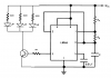
This is board layout:
555 Timer
Pin 1- To Ground
Pin 2- Jumper to Pin 6, Jumper to Base of NPN
Pin 3- 10k resistor to base of NPN
Pin 4- Jumper to Pin 8
Pin 5- NC
Pin 6-Jumper to Pin 2
Pin 7-NC
Pin 8-Jumper to Pin 4, Connected to Positive voltage
Emitter of NPN to 100ohm resistor to LED
Base of NPN to + side of 220µF cap, then ground - side
Collector of NPN to + voltage
Please watch:
[video]http://s182.photobucket.com/albums/x216/Mouse51180/?action=view¤t=VIDEO0008.mp4[/video]
This is board layout:
555 Timer
Pin 1- To Ground
Pin 2- Jumper to Pin 6, Jumper to Base of NPN
Pin 3- 10k resistor to base of NPN
Pin 4- Jumper to Pin 8
Pin 5- NC
Pin 6-Jumper to Pin 2
Pin 7-NC
Pin 8-Jumper to Pin 4, Connected to Positive voltage
Emitter of NPN to 100ohm resistor to LED
Base of NPN to + side of 220µF cap, then ground - side
Collector of NPN to + voltage