Continue to Site

Welcome to our site!

Electro Tech is an online community (with over 170,000 members) who enjoy talking about and building electronic circuits, projects and gadgets. To participate you need to register. Registration is free. Click here to register now.

  • Welcome to our site! Electro Tech is an online community (with over 170,000 members) who enjoy talking about and building electronic circuits, projects and gadgets. To participate you need to register. Registration is free. Click here to register now.

Stop PWM with output low - (Simplest restart included)

Status
Not open for further replies.

atferrari

Well-Known Member
Most Helpful Member
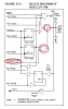
Micro 16F628 - A PWM signal used to control a DC motor, requires, when stopped, to have the PWM output pin (RB3) low.

Initially, I (wrongly) tried BCF T2CON,TMR2ON but realized that the output stays high, most of the times, so I resorted to add CLRF CCPR1L. Still the same problem :?: :!:

From the manual: The CCP1 pin is set (exception: if PWM duty cycle = 0%, the CCP1 pin will not be set)

Question a) What could be the reason I don't get that result?
-----------------------------------------------------------------------
Later, with CLRF CCP1CON i've got the output becoming low.

Question b) Is there a simpler way than CLRF CCP1CON to stop the PWM with output pin low?

To restart I have to set it up again as PWM (could I avoid this?) and then, if needed, to reload b4:b5 with the LSB of the duty cycle value. I feel that changing the setting of a peripheric to stop it, is not correct (or at least, excessive!!)
 
Can you afford to wait for the PWM to go low and stop the timer then?

BTW, I'm just looking over your shoulder, scratching my head with you. I don't know much about PWM yet, just throwing guesses at you trying to help, and maybe learn at the same time... ;)
 
Immediate stop

What I want is to stop, "right now" (that's why the first option - stopping TMR2 - doesn't work most of the times because my duty cycle is 80% of the period).

Should be a simpler way... :cry:
 
Why don't you just set TRISB,3 bit to make that pin an input? That would definitelly stop your motor (without affecting PWM settings).
 
Jay.slovak said:
Why don't you just set TRISB,3 bit to make that pin an input? That would definitelly stop your motor (without affecting PWM settings).

Say he sets the TRISB bit to 1, since the latch is shared between the I/O pin and the PWM, would he need to make sure the PORTB bit is set to 0 to avoid sinking current? Or is the I/O automatically blocked when you are using PWM? It's not clear from the datasheet.
 
That might be a problem, on the picture we see that output buffer is activated when there is a LOG0 on it's Enable input, and the AND gate that controlls it.
 

Attachments

  • latch.png
    latch.png
    31.9 KB · Views: 642
Ahh, I had missed a part of it when first checking the datasheet. OE didn't ring a bell at all. It's all in the note though. Somehow it's pretty obvious now with the red circle around the AND gate :lol:

So it looks like simply setting the TRISB bit as 1 would work, and making sure the OE bit is cleared would avoid problems...
 
1. If you set the period to 0 the cycle should finish and it should stay low. Note a few revisions of PIC chips have defects in their PWM with 0% or 100% duty and you should check those sheets.
2. If you reconfigure that CCP module as being disabled you can write the pin to 0 immediately. I don't see myself why you would need such an immediate response, a motor doesn't respond really quick so cutting a cycle a few mS short wouldn't make much difference.
3. Aren't you using some sort of driver? Setting the TRIS bit to 1 may not get you an immediate response especially if it's a MOSFET. If you're driving it directly setting the TRIS bit may harm the PIC because the motor's inductance can make a high voltage spike that isn't conducted to ground.

And note the difference between cutting off the power to a motor's drive and grounding the motor. If you ground it then it stops much faster.
 
Problem solved

Thanks to you all for replying.

Found the reason of the problem: I was stopping TMR2, what I shouldn't. :cry: CCPR1L was properly cleared but counting was already disabled.

Now I can say: Joel, take notes, the right way to get the output low is making CCPR1L and CCP1CON b5:b4 = 0.

In my case, CCP1CON b5:b4 are always =0 so CLRF CCPR1L is enough.

Once I write the new duty cycle value, other than 0, the output pin goes high.
 
Re: Problem solved

atferrari said:
Thanks to you all for replying.

Found the reason of the problem: I was stopping TMR2, what I shouldn't. :cry: CCPR1L was properly cleared but counting was already disabled.

Now I can say: Joel, take notes, the right way to get the output low is making CCPR1L and CCP1CON b5:b4 = 0.

In my case, CCP1CON b5:b4 are always =0 so CLRF CCPR1L is enough.

Once I write the new duty cycle value, other than 0, the output pin goes high.

Cool, thanks for sharing your results ;)
 
Status
Not open for further replies.

Latest threads

New Articles From Microcontroller Tips

Back
Top