Hi all,
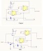
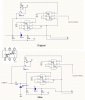
Well I have be trying to sort a problem with a comms probs / injector I have made, I have attached the schematics from my original (working) design and the new design that attempts to solve a problem I have whilst sometimes hitting a high voltage line (24v) or GND whilst transmitting and blowing parts up.
This circuit is used to monitor comms on a test board and occasionally inject a command overriding anything else on the RX/TX line by forcing the line high and low in time with my command, the line is held high (5v 50ma) and all other devices are connected with bipolar transistors. When another device is transmitting and I want to override it I have to be able to supply 1.5A to ensure it's held high I do this with the FMMT717.
The new design attempts to limit the voltage with a 5.1v zenner and a current limiting resistor 100R, this is derived from 24v / 250ma = 96R as the zenner can only handle 250ma max. You will also notice a change in base resistor on the FMMT717 but I think this still is incorrect and should be 10R (5v) to ensure MAX output of 2.5A.
This has been driving me mad! I have had some great advice so far but tried to do it myself so I learn, I think I'm almost there and maybe it's only the use of a FMMT717 and not a FMT720 (capable of a base voltage difference of -40v and not -12 as with the FMMT717)
So, to clarify, what I want to do is, monitor comms, "force" a command onto the line, not blow parts when either hitting a 24v line or GND whilst transmiting a command.
Hope this all makes sense.
Thanks
p.s. The Pullup control and RX/TX are connected to a MCU
")
