Maverickmax
New Member
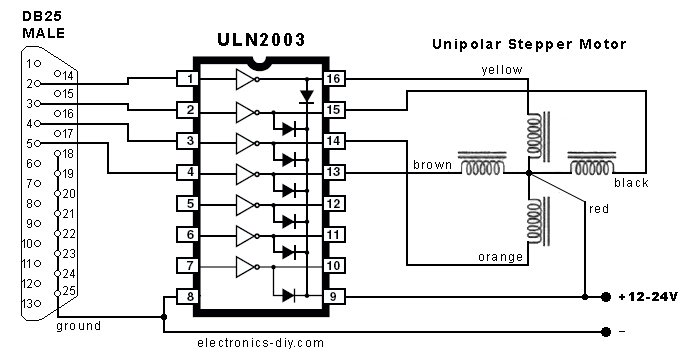
At the moment, I am using a mimusi stepper motor which contains five wires: red, black, orange, brown and yellow.
So far, I use the sequence: 0x01,0x02,0x04,0x08 at 12 times in order to complete one revolution with my AVR chip. It works well then I tried to reverse the direction and to my surprise, it still goes in the same direction instead of going backward.
Forward
Pin 16 of ULN2003 - Yellow - 0x01
Pin 15 of ULN2003 - Orange - 0x02
Pin 14 of ULN2003 - Brown - 0x04
Pin 16 of ULN2003 - Black - 0x08
Backward
Pin 16 of ULN2003 - Yellow - 0x08
Pin 15 of ULN2003 - Orange - 0x04
Pin 14 of ULN2003 - Brown - 0x02
Pin 16 of ULN2003 - Black - 0x01
I could not understand why. Any suggestion?
MM