Continue to Site

Welcome to our site!

Electro Tech is an online community (with over 170,000 members) who enjoy talking about and building electronic circuits, projects and gadgets. To participate you need to register. Registration is free. Click here to register now.

  • Welcome to our site! Electro Tech is an online community (with over 170,000 members) who enjoy talking about and building electronic circuits, projects and gadgets. To participate you need to register. Registration is free. Click here to register now.

Step up transformer for Piezo Buzzer circuit

Status
Not open for further replies.

dk-info

New Member
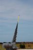
I need a very loud (120 dB) "buzzer" for high power rocket recovery.

I found a circuit on the web for a Piezo driver. From what I understand, The circuit is a CMOS buffer arrangement into an oscillator (about 3kHz), driving a step up transformer, feeding the Piezo speaker. I am looking for a 1:10 step up transformer (Secondary 200 mH) for the circuit.

Looking on the web, I was not able to find a 200mH inductor (I was hoping to hack this into the transformer I need).

1st question: Does someone know of a source for a 200mH toroid inductor?

Barring that I thought I would try to wind my own:
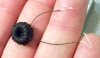
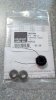
I did find some sources of Ferrite toroids (FT50-J), (Universal Radio) with a material ("J" material) that would take only a few hundred turns to make up the 200 mH I need:

N = 1000 * √([inductance needed]/Aj)

For the "J" material, Aj = 2710, n ~= 271 turns.

Assuming my theory is somewhat correct, I need some practical advice.

I selected the FT50 size to keep the overall size manageable, and was thinking of using 30 AWG wire wrap wire for the conductor.

I do not have an idea how to wind the toroid (in a practical way).

I have seen thin, long shuttles small enough to pass through the toroid, holding the conductor. The problem I foresee is the 30 AWB wire will fill up the FT50 pretty quickly (will it even fit?), not allowing room for a shuttle to pass.

I do have some fine "bell wire" 134-AWN, but I do not know how much current it can handle.

2nd question: Does anyone have any experience hand winding a toroid transformer?

3rd question: I am not familiar with the wire size 134-AWN; how much current could I manage if I ended up winding the transformer with this wire?

Thank you in advance for your help.

David W. Space Coast, Florida
 
hi David,
Do you have a link to the CMOS osc/buffer circuit, depending upon the CMOS devices it may not be able to drive a 1:10 step transformer.??
What sort of weight and size limitations do you have for the buzzer equipment.?
 
Last edited:
I was in my local Pound Shop (translation: Dollar Store) just 2hrs ago and noticed they stocked personal alarms advertised as 120dB output. Suitable? Cheaper than building one.
 
Rugged beeper - noise makers for high power rocket recovery.

hi David,
Do you have a link to the CMOS osc/buffer circuit, depending upon the CMOS devices it may not be able to drive a 1:10 step transformer.??
What sort of weight and size limitations do you have for the buzzer equipment.?
It came from "Discover Circuits" By David Johnson, **broken link removed**,

He has other beeper circuits. As for buying alarms from the local Dollar (Pound) store, I have seen literally dozens of alarms fail for one or another reason during the rocket flight/recovery. (we have typically 350 - 400 kg of thrust, and the rockets reach heights of 1.5 - 2.5 km, often reaching Mach 1.2) I want to build a bullet proof, very loud piezoelectric based pulsating alarm to help find my rocket in the tall bushes here in Central Florida where we launch.

Any insight into winding toroids or to the circuit is appreciated.

David W. Space Coast, Florida.
 
Something you need to watch along these lines is how loud something actually is. Here is what I am getting at. For me to say that an acoustic device puts out 100 db or 120 db or whatever db fails to tell the whole story. If I say 100 db @ 2' I have defined a distance. So 100 db at 1" isn't the same 100 db @ 2'. As to commercial solutions at low voltages these are a good off the shelf line. They run from simple to more complex sounds. This eliminates the need for building a small power supply and oscillator to drive the thing. While not cheap at about $25 USD they are likely much less expensive than replacing a rocket. Anyway, something to think about. I use the Mallory Sonalert line in high vibration areas and never had one fail. They are rugged and commercial.

Before I forget:

It came from "Discover Circuits" By David Johnson, **broken link removed**,

That link is incomplete and doesn't seem to work fro me.

Ron
 
Last edited:
I have seen literally dozens of alarms fail for one or another reason during the rocket flight/recovery.
Can you tell us the failure modes? I would guess that a likely cause would be detachment of the heavier components from a circuit board. In the case of a small personal alarm any IC and passive components would surely be SMD parts able to withstand rocket g forces and the heaviest component would be the battery; so if that could be given additional support (hot melt glue?) such an alarm would be 'bullet-proof' (unless the rocket ends up immersed in an Everglades swamp!)
 
I also agree that the LOUD 120dB spec's for piezo alarms are a joke. They are 120dB only if you hold the alarm directly on the burglar's ear.
A few metres away they are just a little sound.
 
Thanks CZ, it looks like he used a DC-DC inverter type transformer with a 10:1 turns ratio. Then he mentions the hack on the transformer. I hate trying to work from drawings like that. It gets frustrating as all hell.

Ron
 
How loud is Loud? Or - How to beat the bugs at their own game. A Loud Piezo Beeper

Can you tell us the failure modes? I would guess that a likely cause would be detachment of the heavier components from a circuit board. In the case of a small personal alarm any IC and passive components would surely be SMD parts able to withstand rocket g forces and the heaviest component would be the battery; so if that could be given additional support (hot melt glue?) such an alarm would be 'bullet-proof' (unless the rocket ends up immersed in an Everglades swamp!)

First and foremost the initial acceleration along the long axis of the rocket. The common use is to stuff the alarm in any which way you can, using hot melt glue and gaffer's tape. The larger components (electrolytic cap, and piezo element, 9V battery rip off from the mounts provided, mostly solder points) Any plastic housings with self taping screws fail next. I have mitigated the large component problem with epoxy and conformal coating of all components. The next trick is to change the axis of acceleration so the moments of inertia of the large components are directed in parallel with the long axis of the rocket. When all is said and done, the hacking and cutting, gluing and praying, I would rather spin my own.

Along with the mechanical challenges, the actual sound output is masked by the environment; bushes, grasses and the actual direction of the sound opening of the beeper when it is on the ground. This is further exacerbated by the behavior of the local insects. They have a tendency to make a sound in the 1kHz to 3kHz range any time you get near them. The result is a 105 dB (measured at 10 meters) wall of sound, masking any directionality. The insects will mimic the sound of the beeper, matching slower frequency shifts. Very frustrating when you are pushing through the bush looking for your rocket like a Spanish Conquistador in the hot Florida sunshine!

I am trying a slightly different approach. Using the loudest beeper circuit I can build with a 9V source, modulate the output to beep out 13 WPM Morse code, like “SMR” (save my rocket) in a repeating sequence. Just let the bugs mimic that! Ergo the buzzer circuit. I have used the Mallory Sonalert in the past, it is on the large side, drawing 170 mA continuous @9V, even with modulation it has a limited duration.

This brought me to the step up transformer driving the piezo element. If I can drive a piezo at its limit (30 – 100V), do a slow Morse like modulation, and control the mechanical issues by design, I might have a reasonable solution.

My first attempt at winding a torpid was less than stellar. Using a FT50-J ferrite toroid I was only able to wind 100 turns of 30 AWG wire wrap wire. It yielded 41 mH @ 1 kHz. By the calculations I should have seen on the order of 74 mH.

Getting back to the electronics, what am I doing wrong with the transformer? If all I need is a 1:10 step up, how critical is the actual inductance? I could easily fit 80 turns of the secondary and 8 turns of a primary with the 30 AWG wire on the 12.5 mm toroid.

Thanks with your kind patience with my ignorance.

David
 

Attachments

  • 2011-10-08_07-29-56_153.jpg
    2011-10-08_07-29-56_153.jpg
    720.2 KB · Views: 637
  • 2011-10-08_07-28-56_73.jpg
    2011-10-08_07-28-56_73.jpg
    2.1 MB · Views: 506
  • 68b0c37f6d76908b3f49e04567270a39.jpg
    68b0c37f6d76908b3f49e04567270a39.jpg
    87.6 KB · Views: 413
  • 8d75cf98458f1783c764af9ac8245040.jpg
    8d75cf98458f1783c764af9ac8245040.jpg
    99.4 KB · Views: 412
Calculate the sound pressure:
120dB at 12 inches.
114dB at 24 inches.
108dB at 48 inches.
102dB at 8 feet.
96 dB at 16 feet.
90dB at 32 feet.
84dB at 64 feet.
78dB at 128 feet and you might not hear it if there is any background noise.
 
My first attempt at winding a torpid was less than stellar. Using a FT50-J ferrite toroid I was only able to wind 100 turns of 30 AWG wire wrap wire.
Use magnetic wire with an enamel coating. You will be able to fit alot more wire in the same space.
 
Use a high voltage transistor and 10mH inductor. It will be smaller and lighter.
The peak output will depend on getting the resonant frequency correct.
 
Use a high voltage transistor and 10mH inductor. It will be smaller and lighter.
The peak output will depend on getting the resonant frequency correct.

Greetings.

I am afraid I do not have the chops to translate your comment into a circuit I can build. Would you be so kind and sketch out an example circuit?

Cheers!

David - from the "other Melbourne"! (Florida of course)
 
Status
Not open for further replies.

Latest threads

Back
Top