Continue to Site

Welcome to our site!

Electro Tech is an online community (with over 170,000 members) who enjoy talking about and building electronic circuits, projects and gadgets. To participate you need to register. Registration is free. Click here to register now.

  • Welcome to our site! Electro Tech is an online community (with over 170,000 members) who enjoy talking about and building electronic circuits, projects and gadgets. To participate you need to register. Registration is free. Click here to register now.

State-variable filter simulation problem......

Status
Not open for further replies.

Learner

New Member
Hi guys,
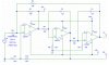
I am trying to build a state-variable audio filter and it simply just doesnt work as it should, by changing R3 and R4 it suppose to change the cut off frequency but I've simulated and built it on the breadboard they both seems to get the same result.

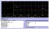
Bandpass don't appears to work as bandpass and highpass don't work as highpass, well hipass actually have the same response as bandpass :?

Something is just not right and I do not know what it is, can somebody help me!!! :(

Thanks in advance!
 

Attachments

  • sim_copy.jpg
    sim_copy.jpg
    74.1 KB · Views: 600
  • circuit_copy.jpg
    circuit_copy.jpg
    70.6 KB · Views: 688
When you start with LP feeding into a HP will give BP. It appears that you have it the wrong way around?
 
Well, that's what it appears to be on the book Active-Filter Cookbook I have and also here on maxim-ic's
**broken link removed**

I don't understand how IC1 can be a hi pass filter when it is just an non-inverting op amp configuration, I am currently very lost on this right now...... :oops:
 
Oh, the answer is, the summing node. Sorry, I only looked at what stage was going into what without analyzing properly.
 
?

Sorry, please elaborate....

Do you mean I need to sum the HP, LP and BP together into the same output?

Also, by changing R3 and R4 am I simutaneously changing the LP and HP cut off point as well as the BP 3db cut off point?

Thanks!
 
Before you go any further, you have the polarities of the inputs +/- mixed up. That is your problem :!:
 
That is what had me fooled, I did not recognize it as the classical "universal" active filter.

Advantage of this is 2nd order response for LP and HP but difficult to obtain flat respone from BP with values selected for high Q
 
Hi,
I have corrected the circuit but still the simulation response just dont look right.........sigh........ :(
 
This is how I remember this setup. The first stage is somewhat different to yours. (Ignore my values as I just used the program's default drawing values)
 

Attachments

  • filter_141.gif
    filter_141.gif
    8.6 KB · Views: 549
It works in SwitcherCAD III. See below.
Edit:
Oops! I didn't notice that R12 (R5 in my schematic) is 20k. I tried that - it changes the response slightly, but still works. The One's configuration gives the same amplitude curves, but with different phase relationships.
 

Attachments

  • statevar_wav.gif
    statevar_wav.gif
    12.2 KB · Views: 480
  • statevar_sch.gif
    statevar_sch.gif
    5.9 KB · Views: 505
Variation in R5 should alter the Q of the circuit
 
I have simulated it in the past, but not recently. I know it works as also established by Ron H in his post.
 
Right, thanks.

I am just trying to find out if Orcad Pspice student version is not able to simulate correctly or it's something that I am not doing right .......... Can someone that uses Orcad student version confirm this?

Thanks in advance!!
 
Status
Not open for further replies.

Latest threads

Back
Top