hello : )
i receieved a nice little relay in the post today, im sure if i blew it up (due to misleading websitedata) or have a current problem??
on the website i bought it from,(see link below) the data section says input control voltage 1.7v
so i thought approx 1.7v would be fine. ( i think i may have given it 1.85v at max)
anyway the relay did not work , i thought oops : i then download the official data sheet and it says :
Input Forward VF (volts)
min1.1
typ1.3
max 1.65
so i now think,oh boy, did i over cook it?
the reason i send this message on the board is that i am not an expert and the way i get my voltage is via a 2.5v regulator and i drop the volts using approx 5 M ohm resistor. i am not near my breadboard to give the exact ohms rating which i used but via my multi meter the voltage i had when it was not connected to the relay was about 1.75v. Is this wise ? Do you think my amps could be too low due to the large M ohms i use?
anyway i have reordered the same relay again and shall try 1.3volts instead, but that means i will need much more resistance maybe 7>8M ohms to get 1.3v??
any thoughts would be great
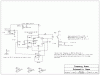
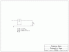
here is the relay, it is a dual/ double relay in one package. Avago Technologies | Relays, Switches and Indicators | Relays | PCB Solid State Relays (SSR) | PCB Mounting SIL, DIL & SMT |ASSR-1420-002E
i receieved a nice little relay in the post today, im sure if i blew it up (due to misleading websitedata) or have a current problem??
on the website i bought it from,(see link below) the data section says input control voltage 1.7v
so i thought approx 1.7v would be fine. ( i think i may have given it 1.85v at max)
anyway the relay did not work , i thought oops : i then download the official data sheet and it says :
Input Forward VF (volts)
min1.1
typ1.3
max 1.65
so i now think,oh boy, did i over cook it?
the reason i send this message on the board is that i am not an expert and the way i get my voltage is via a 2.5v regulator and i drop the volts using approx 5 M ohm resistor. i am not near my breadboard to give the exact ohms rating which i used but via my multi meter the voltage i had when it was not connected to the relay was about 1.75v. Is this wise ? Do you think my amps could be too low due to the large M ohms i use?
anyway i have reordered the same relay again and shall try 1.3volts instead, but that means i will need much more resistance maybe 7>8M ohms to get 1.3v??
any thoughts would be great
here is the relay, it is a dual/ double relay in one package. Avago Technologies | Relays, Switches and Indicators | Relays | PCB Solid State Relays (SSR) | PCB Mounting SIL, DIL & SMT |ASSR-1420-002E