Continue to Site

Welcome to our site!

Electro Tech is an online community (with over 170,000 members) who enjoy talking about and building electronic circuits, projects and gadgets. To participate you need to register. Registration is free. Click here to register now.

  • Welcome to our site! Electro Tech is an online community (with over 170,000 members) who enjoy talking about and building electronic circuits, projects and gadgets. To participate you need to register. Registration is free. Click here to register now.

Spice question - small signal gain.

Status
Not open for further replies.

alphacat

New Member
Hello.

I've drawn an CS amplifier as can be seen in the scheme.
I'm not sure what should I fill in these two fields in order to receive the small signal DC gain of this amplifier.
I'd love to receive help regarding that,

Thank you very much.

small-signal-jpg.30957
 

Attachments

  • small signal.JPG
    small signal.JPG
    58.7 KB · Views: 1,434
the first box is the source of the dc "signal / disturbance". what it is depends on what you want to do. For example, this circuit is configured as a common source amplifier. so you want to know how a change in Vgs is going to produce a (bigger) change on the CCS. so the first box should be V1.

the 2nd box is essentially the output you desire from the circuit. it could be voltage on R1(V(r1)), or current on R1 (I(r1)).
 
Hey,

I tried this out, and wrote:
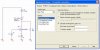
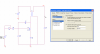
V1 in the upper box.
R1(I(r1)) in the lower box (I also tried writing I(R1), and R1(I(R1))).

I received this error:
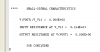
*Analysis directives:

.TF R1(I(r1)) V_V1
----$
ERROR -- Must be independent source (I or V)
.PROBE V(alias(*)) I(alias(*)) W(alias(*)) D(alias(*)) NOISE(alias(*))
.INC "..\SCHEMATIC1.net"

Do you have an idea what is the problem?

Thanks.
 
sure.

here is what I did in a sample circuit.

my signal source for this analysis is V13 and my output is voltage on the load R43.
 

Attachments

  • small signal analysis.PNG
    small signal analysis.PNG
    40.1 KB · Views: 556
here is the analysis output:

since my output is going through a transformer, there is no DC content so the gain is 0.
 

Attachments

  • small signal analysis 2.PNG
    small signal analysis 2.PNG
    4.8 KB · Views: 366
Thank you very much :)
It worked out great.

I followed exactly what you have written there - calling the netlist 'Vout', placing a voltage prob on the netlist - otherwise it didnt work.

What would you write if you wanted the Output Variable to be the load (R1) current?

Here is what I wrote, and I received the same error message as before.
small-signal2-jpg.30966
 

Attachments

  • small signal2.JPG
    small signal2.JPG
    61.4 KB · Views: 1,372
Status
Not open for further replies.

Latest threads

New Articles From Microcontroller Tips

Back
Top