Continue to Site

Welcome to our site!

Electro Tech is an online community (with over 170,000 members) who enjoy talking about and building electronic circuits, projects and gadgets. To participate you need to register. Registration is free. Click here to register now.

  • Welcome to our site! Electro Tech is an online community (with over 170,000 members) who enjoy talking about and building electronic circuits, projects and gadgets. To participate you need to register. Registration is free. Click here to register now.

Speed regulation of DC motor

Status
Not open for further replies.

dekiz77

New Member
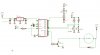
Could anybody check my schemes. The task is speed regulation of DC motor ( just increasing and decreasing speed via potentiometer), turning off and on the motor. I made two schemes so I need suggestions and corrections about them.In first scheme I planed to control the motor reading the pinRB6 ( potentiometer value) and in the other with transistor, capacitor and potentiometer ((TR1 becomes ON condition when RB7 becomes H level. In this condition, the electric charge of capacitor C1 flows through the transistor and the voltage of the both edges of the capacitor becomes 0 V almost.
When RB7 becomes an L level, the transistor becomes OFF condition. In this condition, the electric current flows through VR1 and R4 into capacitor C1 and the charging to the capacitor begins. The voltage of the both edges of the capacitor becomes high gradually as charging is done.The voltage of the capacitor is detected by RB5. The software of PIC interrupts the control of the motor until it checks RB5 after making RB7 an L level and RB5 becomes H level. When making the value of VR1 small, the charging time of the capacitor is short and the control of the motor becomes quick. The control of the motor becomes slow when making VR1 big. The speed control range can be changed by changing the value of the capacitor.))
 
Here are my schemes. And I need one information about dc motor : I found a toy train and I plan to use the dc motor form it but there are no information about the voltage or any other information.
 

Attachments

  • Speed regulation1.jpg
    Speed regulation1.jpg
    40.8 KB · Views: 767
  • Speed regulation2.jpg
    Speed regulation2.jpg
    50 KB · Views: 522
Your diagrams look OK except that the flyback diode should be across the motor instead of the transistor. You also appear to have Vdd as both your unregulated and regulated supply, it might be safer to label them 12V(or whatever) and 5V. For an example of reading a potentiometer by charging a capacitor, have a look at especially the joystick board and tutorial 4.

Mike.
 
Thanks for advice. About Vdd: I was in haste when I drew the schemes so I just skiped the values. My main problem was the position of diode, and the arrangement of the other components especially of the potentiometer on the speed speed regulation2 image.The motor I plan to use is brushed DC motor from toy train.
 
The scheme in image 2 will not work. You need the components arranged in the order Vdd - potentiometer - capacitor - gnd and the pic pin connected to the potentiometer/capacitor junction. You don't need the BD239 to discharge the capacitor. To read the potentiometer you set RB7 to output and set it low to discharge the capacitor. You then set it to input and time how long it takes to become logic high again. The longer it takes the higher the value of the potentiometer. The capacitor you use should be small - about 0.1uF.

Mike.
 
Yes I have to work with PIC, and I'm a beginner in microcontreller world so it's a little bit difficult to me.Mike, should this scheme work?
 

Attachments

  • correction.jpg
    correction.jpg
    52.7 KB · Views: 330
As Nigel said, it should work OK. However, I would keep a small resistor in series with the pot. Something like a 10k pot and a 1k resistor in series should do.

Mike.
 
giaosucan said:
I've never seen the schematic like it before .In my opinion ,to regulate speed of DC motor ,you should use H-bridge or relay circuit .Using this circuit ,you can control speed ,direction of DC motor ,and other..v.v
I think it is difficult for you to control DC motor using your schematic.

What he has is effectively ¼ of a H-bridge and he will have the same control over the motor speed as a full H-bridge would have. You only need a full H-bridge if you want to reverse.

Why do you think he will have difficulty?

Mike.
 
Pommie and Nigel thanks, you've helped me a lot. I attached the final circuit image considering or the advices ( about components values...).I will try to do a scheme with H-Bridge for my other project(but as Pommie said that would only have sence if I want to reverse the motor direction).
 

Attachments

  • Final.jpg
    Final.jpg
    54.1 KB · Views: 323
dekiz77 said:
Pommie and Nigel thanks, you've helped me a lot. I attached the final circuit image considering or the advices ( about components values...).I will try to do a scheme with H-Bridge for my other project(but as Pommie said that would only have sence if I want to reverse the motor direction).

Yes, only needed if you want to reverse it - and you can do it more simply by using a DPDT relay rather than an H-Bridge.
 
dekiz77 said:
Pommie and Nigel thanks, you've helped me a lot. I attached the final circuit image considering or the advices ( about components values...).I will try to do a scheme with H-Bridge for my other project(but as Pommie said that would only have sence if I want to reverse the motor direction).
Tell me...is your purpose to learn the PIC or to control the motor?

Dan
 
I want to learn PIC ( that is my aim ) but my knowledge about motor is not so goood so I had to ask for some help. These days I'm writing a micro Basic program for DC motor control...Because I'm a beggginer it's not so easy.
 
Status
Not open for further replies.

Latest threads

Back
Top