Continue to Site

Welcome to our site!

Electro Tech is an online community (with over 170,000 members) who enjoy talking about and building electronic circuits, projects and gadgets. To participate you need to register. Registration is free. Click here to register now.

  • Welcome to our site! Electro Tech is an online community (with over 170,000 members) who enjoy talking about and building electronic circuits, projects and gadgets. To participate you need to register. Registration is free. Click here to register now.

Special Latching Relay Help Needed

Status
Not open for further replies.
Hey fellow techies...I need some help with creating a latching relay to keep this siren/strobe unit going once it receives power via this fail safe closed loop circuit. Anyone have any suggestions?

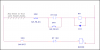
When the door switch is open or the wire is cut, CR1 drops out and CR1 contacts are closed providing power to the Siren/Strobe. I need to create a latching circuit that will keep the Siren/Strobe going even when the door is closed and the system is restored to normal conditions. Then I need to incorporate a "Reset" button into the system to kill the Siren/Stobe. I need to do this using ice cube relay's that are din rail mounted / 12vdc. Can someone point me in the right direction on how this would look on paper?


**broken link removed**
 
Last edited:
They make latching relays. I have one in my hand that has one coil. There is a verson with two coils, one to force on, and a second to force off.

If you need to use your "cube relay on din rail" then; what is it's part number?
 
You only need one more relay: the classic "locked-out" relay circuit to the rescue!

**broken link removed**

Just replace S1 in this diagram with your existing relay (CR1) contacts. When that relay closes, it will energize this relay, which is self-latching, so no need to buy special relays. Pushing S2 (normally-closed pushbutton) will shut off the alarm.

That is, if I understand your problem correctly ...
 
Thanks Carbonzit...That circuit seems to work, though in my circuit the "off" button has to be open when you turn on power to the system initially or it sets off the alarm for some reason. Basically you have to turn everything on and then close the off button.
 
Last edited:
The attached circuit is along the lines of the circuit that carbonzit posted and should do as you want. The relay can be any 12 volt coil DPDT relay. When SW1 is pressed RY1 will pull in. That action will close the RY1 N/O contacts in parallel with SW1 and latch RY1 in an on state. The RY1 N/C contacts in series with the buzzer/alarm will be open and SW3 can be closed. I guess we could say the circuit is armed as that sounds cool. :)

Any break in the line marked will unlatch RY1 and the alarm will sound, the same is true if we push SW2 the N/C push button switch (SW1 and SW2 are momentary push button switches) SW2 is a "Push To Test as that also sounds cool to say. :)

Once the relay is unlatched the alarm will continue to sound, even if the line is closed until SW1 is pressed to reset RY1. That about what you want?

Ron
 

Attachments

  • Latch Relay 1.png
    Latch Relay 1.png
    13 KB · Views: 204
@reloadron,

...and what might that nifty little diode be doing? Indicator light?

Yeah, that nifty little diode is like a 1N4002 as a snubber for what carbonzit said. However, we could add some LEDs for armed and alarm status. :) Actually though not likely needed we could add a relay so the audible could be turned off but a light would remain lit during alarm condition. :) When complete relays and buttons will be your new best friends.

Ron
 
Status
Not open for further replies.

Latest threads

New Articles From Microcontroller Tips

Back
Top