Electro Tech is an online community (with over 170,000 members) who enjoy talking about and building electronic circuits, projects and gadgets. To participate you need to register. Registration is free. Click here to register now.
Welcome to our site! Electro Tech is an online community (with over 170,000 members) who enjoy talking about and building electronic circuits, projects and gadgets. To participate you need to register. Registration is free. Click here to register now.
So i bought this kit: **broken link removed** i can get both lights to work but i cant get the speaker to make a sound... any idea on how i can troubleshoot this??
First, using an ohmmeter, check to make sure that all solder joints have continuity. Then you look at the schematic and follow the path of the signal going to the speaker. Then you try to trace the signal with an AC voltmeter or oscilloscope to see where the signal break is occurring.
Of course every solder joint has to have continuity through it, otherwise it's a bad joint. That's the purpose of the solder joint. How could the circuit work if there's not continuity through all the specified connections?
The purpose of the solder joint is to electrically connect the component with the circuit. For the solder joint to do its job, it needs to have continuity thorugh it. That doesn't mean that every solder joint should have continuity with every point in the circuit. To test if you have a good solder joint, place one lead of the ohmmeter on the lead of the component on the top side of the circuit board, then place the other lead of the ohmmeter on the trace directly next to the solder joint on the reverse side of the circuit board. If the joint is good, there should be continuity. Also, make sure that the polarized capacitors are installed the correct way. You can also test the speaker by measuring the resistance across its inputs. It will probably be 4,8, or 16Ω.
i will test circle with circle and square with square right?? and if i hear a beep on my multimeter that means it has continuity... If yes i did this already and every solder joint has continuity with at least another solder joint
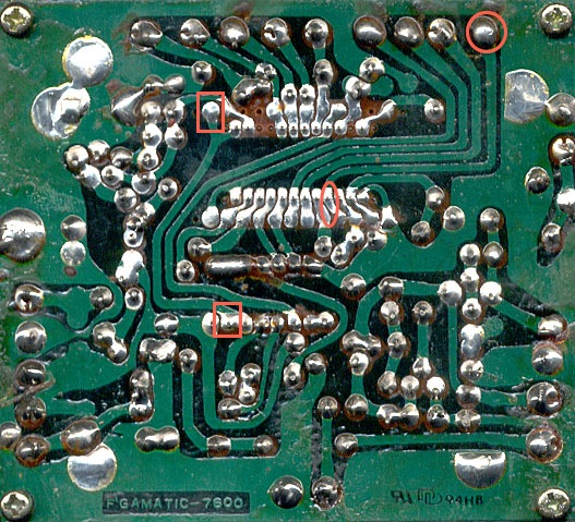
No, that's not right. By doing that check that you are depicting in the photograph what you are actually checking in continuity of the circuit board trace, not of the component to the trace. What you want to make sure is that the components that you soldered in place are electrically connected to the circuit board traces. Measure between point A and B like in the picture. That will tell you if you have a good solder joint of not. Make sure the lead on your multimeter is getting through the green coating over the traces. Also, make sure that there aren't any solder joints that are so messy they connect parts of the circuit that shouldn;t be connected.
while doing the continuity test when i touch point a and b on everything makes a beep so i guess is connected right.. but speaker still not working :S
i also tested the speaker on my arduino board and it works fine
If you got continuity at every solder joint that means that each joint is good enough but it doesn't necessarily mean that everything is connected right. I assume you made sure the electrolytic caps were in the right way and also that you didn't have any solder blobs so big that they are touching adjacent pads or traces? If you did I would next turn my attention to the 555. Maybe you got it too hot when soldering.
could you post a pic of both sides of your board? Double check the polarities of your components. The test you were doing before wouldn't be a bad test to check and make sure the copper track isnt broken. It's possible you got the board too hot and the copper pulled away from the board. Also, start from the speaker and work it back until you have voltage potential. Just leave one of your multimeter leads on the - and jump from point to point starting with the speakers +
could you post a pic of both sides of your board? Double check the polarities of your components. The test you were doing before wouldn't be a bad test to check and make sure the copper track isnt broken. It's possible you got the board too hot and the copper pulled away from the board. Also, start from the speaker and work it back until you have voltage potential. Just leave one of your multimeter leads on the - and jump from point to point starting with the speakers +
Change your voltmeter to 20V. Put the negative (black) lead on ground and keep it there and then just work your way back from the speaker with the positive(red) lead until you see some voltage like scarygood says. When you see some volatge, that will be close to where your problem is.
According to the schemaatic, there are only three possible bad connections: pin 3 of the 555 to the 1ouF cap; from the cap to the pot; and from wiper of the pot to speaker. What, if anything, do the instructions say?
This site uses cookies to help personalise content, tailor your experience and to keep you logged in if you register.
By continuing to use this site, you are consenting to our use of cookies.