Continue to Site

Welcome to our site!

Electro Tech is an online community (with over 170,000 members) who enjoy talking about and building electronic circuits, projects and gadgets. To participate you need to register. Registration is free. Click here to register now.

  • Welcome to our site! Electro Tech is an online community (with over 170,000 members) who enjoy talking about and building electronic circuits, projects and gadgets. To participate you need to register. Registration is free. Click here to register now.

Sound to Light, Advice Please

Status
Not open for further replies.

Fenris

New Member
hi all

ive been playing around with this design for a while and
am ready to commit to a PCB. but first could you chaps
just advise on my final setup please. basically the front
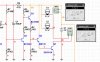
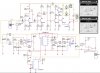
end of the circuit originally was a sound to light vellerman
kit that drove 4 LED's in series on the emitter of the BC558.
what i have done is replace them with a BD139 to a 2N3055
to drive a parallel pair of 12V 24W bulbs. the circuit will of
supplied by 12V DC 45Ahr car battery. originally i was using
a pair of TIP41C transistors driven by the BD139 with 1 bulb
driven by one TIP41 each to share the load. but i have now
found the 2N3055 which is rated a lot higher and can handle
the load with a more generous reserve. i have run the circuit
on a national instruments simulator and it seems ok. my problem
is my maths is, frankly, not up to snuff with this sort of thing, i
can do ohms law but i lack the intuitive application of said data.
so given the supplied data on the attached pic is everything ok?

also im trying to work out heatsink size, the 2N3055 will be mounted
on the exterior of the case so my effort at calculating it is as follows;

3.8A x 12V = 45.6W
Max juncion temp is 200C
total Dissapation @ Tc < 25C is 115W
junction to case Th r is 1.5C\W + 0.5C\W for the insulator and paste.

therefore

200C - 40C (worst case safety margin) / 46W (my calculation)
= 3.49C\W - 1.5C\W + 0.5C\W = 1.49C\W

so i need a heatsink rated at :ltoet: 1.49C\W

the heatsink i have found is rated at 1.65C\W
so a little higher than recommended but given the safety margin
probably ok. have i done the maths ok?

i have breadboarded the circuit but only with a 1Ahr 12V
battery so although it worked with the 1 TIP41: 1bulb pairing
design, the run time due to Amps drawn was only 35mins. but
was consistant with each attempt after recharging. a car
battery should run for at least a day. obviously as the bulbs
are flashing at a variable rate then the Amps drawn at any given
point will vary a lot so hopefully the worst case scenario is accounted
for.

all help advice gratefully received. cheers

Fenris
 

Attachments

  • S2L.JPG
    S2L.JPG
    124.2 KB · Views: 172
Where do we start?

The BD139 is driving an unlimited amount of current into the base of the 2N3055. Then the BD139 might smoke and burn.

Q3 is upside-down (its output is its collector, not its emitter) but it would just smoke and burn anyway when it tries to drive 1A into the 10 ohms of R2. The max allowed current for a BC558 is 100mA. The Velleman circuit used 47 ohms to drive only 20mA into the 8V LEDs from a 9V supply.

Q4 has a 100 ohm resistor at its collector that will try to draw 120mA but its 1.5M base bias resistor doesn't provide enough base current so Q4 might also smoke and burn. The original Velleman circuit used 100k for a reasonably low collector current.

If the circuit is fixed then the 2N3055 transistor won't have 12V across it. The light bulbs will. The 2N3055 will have about 0.4V across it and then it will dissipate only 0.4V x 3.8A= 1.5W, not 46W. It might not need a heatsink, certainly not the huge one you calculated.

1) If the lights draw 3.8A then the 2N3055 transistor needs a base current of 380mA to saturate well. Then a 33 ohm/5W resistor should be from the collector of the BD139 to 12V.
2) The BD139 needs a base current of 38mA to turn on well. Then R2 should be 270 ohms to 330 ohms at 1W, not 10 ohms. R3 can be 1k ohms.
3) The base of the BC558 needs a current of only 1mA to saturate well. Then R4 can be 12k, not 100 ohms.
4) The base current of the BC548C can be only 1uA for it to turn on enough so the 1.5M base bias resistor is fine.
 
hi there thanks for your help. i have made the changes
in the simulator circuit and it all works, so next is to try
real world components i guess. one minor point i have is
R6. i actually had to change this on the breadboard to
a higher rating (in the region of 200-470ohm) because the
variable resistor became ineffective; the lights came on and
stayed on. should i use a larger pot and keep the original
47R or did i do right thing? i attach a new image showing
your recommended changes have i understood your directions?
NB. the AC signal, near the mic, is only so i could get the
circuit firing without recourse to the virtual mic function
which takes ages to process and wont be on the real circuit.

regards

Fenris
 

Attachments

  • VMS2L.JPG
    VMS2L.JPG
    108.9 KB · Views: 144
Last edited:
Your BC558B is still backwards. So it acts like a 7V zener diode and turns on the lights all the time.

Don't change the 47 ohms and leave the pot as it is.
The ratio of R7 and R8 was made for a supply of only 9V so that Q4 is turned off. Q4 might be turned on a little when the supply is 12V. So change R8 to 100k.
 
hi there

i have turned the BC558 upside down in the sim.
and changed R8 to 100K.
the lights come on and stay on without any input.
i have run a sound sample and the lights still react
to it but during silence they remain on. any ideas?

regards

Fenris
 
Sorry, my mistake.
Change R8 to 33k or 27k to make Q4 turn off.
 
Last edited:
thankyou thankyou thankyou
works like a treat and the
Amps drawn have also dropped
significantly to i presume the
circuit is reacting in a faster
(more sensitive)? manner to
sound input? thanks for your
help, im tweaking the PCB for
the extra resistor and noting
all changes in values.
I also looked at the original
vellerman circuit diagram for
the first time since i adapted it
for this project......................
thankyou for telling me about the
BC558 being upside down....how
embarrasing is that!!!! &-O

regards

Fenris
 
Last edited:
hi there

i have recalculated the heatsink given your
data and i now only have to handle 80C/W
(found a application that does the calcs
approx) so i can now mount the 2N3055
on the PCB with a rather nice cage heatsink
that bolts ontop with a matching footprint,
its rated at 7.1C/W. venting will be put in the
enclosure as well.

i have done the calcs with the usual formula
to using the following data just to practice;

Tj 200C -Ambient 40C / 1.5W = 107C/W

Rthj-case 1.5C/W + 0.5C/W (insulator/paste) = 2C/W

107C/W - 2C/W = 105C/W

so a heatsink rated at 105C/W or less is required.
so plenty of choice in pattern and model. if i have
got the hang of the maths.

regards

Fenris
 
hi there
can you just clarify your quote about the ressitor on the collector of the BD139 please.

1) If the lights draw 3.8A then the 2N3055 transistor needs a base current of 380mA to saturate well. Then a 33 ohm/5W resistor should be from the collector of the BD139 to 12V.

do you mean 5W or 0.5W thanks

Regards

Fenris
 
Fenris said:
"1) If the lights draw 3.8A then the 2N3055 transistor needs a base current of 380mA to saturate well. Then a 33 ohm/5W resistor should be from the collector of the BD139 to 12V."

do you mean 5W or 0.5W
It will dissipate over 3.3W so it better be 5W.
 
thanks for that clarification. its taken me about an hour but
i have found a supplier for it. Adjusting the PCB to take this
behomoth of a resistor.........24mm long x 8mm thick!!!!!!!!
it'll stand upright on the board. cheers again.

regards

Fenris
 
You don't need the monster very hot R34 resistor if you connect the transistors as a darlington like this:

EDIT: I didn't correct Q3 which is upaside down.
 

Attachments

  • car lights.PNG
    car lights.PNG
    91.8 KB · Views: 143
now thats just sneaky ;) noted and added to
my list of alternate recommended options.
thanks again for your input.

regards

Fenris

Just run this setup through the multisim
the amps drawn have dropped considerably
down to 1.1A, this is good i think. i know
that the sim prog has limitations so ill just
treat it as an indication rather than absolute.
 
Last edited:
i hope not lolol. ive just run the sim
for longer, the amps may in fact be
as near as the original figures, my
mistake i think :eek: still it all looks good,
im going to make the prototype PCB
with an extra track so i can either
have the 5W resistor or just use a
link wire to the 2N3055. its all good fun.

Regards

Fenris
 
Status
Not open for further replies.

Latest threads

New Articles From Microcontroller Tips

Back
Top