https://www.danielandrade.net/2005/12/06/howto-blinking-leds/#prettyPhoto
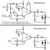
The link above is to a sound reactive LED circuit that i am trying to make, I am using a 12v power supply and 4 LEDs (a green 2.9-3.1v, a blue 3-3.2v, and a yellow and red both 1.9-2v), i plan to connect the circuit to my iPod. But i need help figuring out what resistors to use as limiting resistors and where to put them.
Any help is greatly appreciated.