Continue to Site

Welcome to our site!

Electro Tech is an online community (with over 170,000 members) who enjoy talking about and building electronic circuits, projects and gadgets. To participate you need to register. Registration is free. Click here to register now.

  • Welcome to our site! Electro Tech is an online community (with over 170,000 members) who enjoy talking about and building electronic circuits, projects and gadgets. To participate you need to register. Registration is free. Click here to register now.

Sound level detector circuit

Status
Not open for further replies.

MrDEB

Well-Known Member
I want to compare the output of three different a,ps for my critter ridder
A Bridge amp, no output transistor and a single transistor. Very simple so called amps. Output is a square wave.
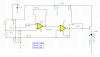
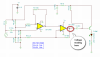
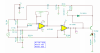
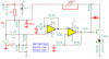
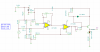
thought about using a lm3616 LED vu circuit but found attached schematic which is supposed to make the LED flash wen the desired db level is reached (R6 is supposed to be a 3 pos switch but planning on just inserting a 10 turn pot.
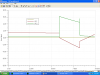
in simulation I can't get the LED to come on. The original circuit used a LM358 op amp. reason for using the TL082 = I have one on hand.
any suggestions ?
original circuit is a room noise detector used search engine (url ?? will locate)
 

Attachments

  • db detector.PNG
    db detector.PNG
    18.3 KB · Views: 658
I inserted a diode across the base to the collector - still won't simulate.
Guess I am going to just have to breadboard the darn circuit. I think the TL082 should work as it is usable for single or duel supply.
 
Hi. What is the optput reading (oscilloscope picture) from the second opamp output?
 

Attachments

  • 46721d1285817878-sound-level-detector-circuit-db-detector2.png
    46721d1285817878-sound-level-detector-circuit-db-detector2.png
    11 KB · Views: 458
circuit mods

I took out the output cap and have 2.5v dc in put for input signal
here is present scope pic
I found a similar thread and it was suggested to remove cap.
I bread-boarded a condenser mic, battery, cap and DMM but didn't get any reading.
All I want to do is compare output performance of the three output amps.
 

Attachments

  • op amp 1.PNG
    op amp 1.PNG
    19 KB · Views: 378
  • op amp 2.PNG
    op amp 2.PNG
    15.3 KB · Views: 292
Another problem I see is that resistor R8 will limit the current so much that the led will probably never light. Even if transistor T1 (should be Q1) is near saturated, the current (assume V_led=2V) will only be around 5 mA.
 
I think the circuit doesn't work because instead of the mic being connected to ground it is connected to the high resistance bias voltage (across C3) so the current in the mic is messing up the bias voltage for the opamps.

I increased the value of R1 and added an RC filter.

The circuit is designed for an electret mic, not a condenser mic but many stores confuse the two. A simulation program does not know a microphone.

R5 and R6 do not need a DC bias voltage so I replaced their connections with capacitors to ground. The value of the capacitors affects the low frequency response.

I added a diode so that C4 does not charge and charge without anything to discharge it. If nothing discharges it then the LED will turn off when it should turn on.

I removed R8.

But I did not remove the chicken pox dots all over the place!
 

Attachments

  • sound level circuit.PNG
    sound level circuit.PNG
    16.9 KB · Views: 437
Will give it a try tomorrow as I am going hunting in the morning. Got to get some sleep
I found a thread where you commented on this same circuit. The op got the circuit working but how good?
Hopefully this will show me which of the three amps for the critter ridder is the best. I feel confident that the H-bridge design is the best but several people from another web site doubt that the H-bridge even works as an amp.
Want to test before making the 1k resistors 330 ohm to reduce the heat.
Plan is to set up a 555 ossciliator and drive each amp. Measure the output with this op amp mic circuit.
maybe by adding a pot for R11 then adjust until led comes on.
will surly post results.
 
couldn't wait till morning

here is revised circuit.
It dawned on me that the LED is going to flash so just a voltmeter won't cut it.
Here is a pic on ossiscope
hopefully adjusting R11 will allow me to adjust for different db levels
Oups I need to put a pot on R6 not R11
 

Attachments

  • op amp3.PNG
    op amp3.PNG
    22.7 KB · Views: 277
  • op amp4.PNG
    op amp4.PNG
    51.4 KB · Views: 258
If you use a pot for R6 then the gain for low frequencies will be changed differently to the gain for high frequencies, unless the capacitor to ground is huge which will take time to charge when the circuit is first turned on.
But a pot for R11 will reduce the gain for all frequencies equally.
I thought your oscillator will sweep frequencies or jump between two frequencies? You can test the sound levels by feeding the amps with a continuous oscillator always at the same single frequency.

I drew my circuit wrong and you copied the error. The emitter of the transistor, D1 and R9 should connect directly to the (+) of the battery, not to C5. Then your 'scope waveform will probably be squarer.
 
I planed on testing using a 555 oscillator set at one frequency. That way ALL the tests should be equal but different results.
will change the connections. I wondered why the 1k but then you know best.
 
I wondered why the 1k but then you know best.
The 1k resistor R12 and C5 make a filter for the bias voltages for the mic and opamps. Without the filter, the battery voltage bouncing from the load's current will cause oscillation.
 
Started searching for my 555 oscillator I conjured up on a perf board but am unable to locate what with all the stuff I have piled up on my work bench.
Need to do some house cleaning before going any further.---lol
 
I don't think I have the mic connected right
RED to V=
White to output and shielded braid to ground (RS 270-092A)
I connected red to V+
shield to ground and meter to output = zero when I turn on the 555 oscillator/tweeter
using the schematic you posted, if I directly connect the 555 output to pin 3 of the first op amp I should get the LED to light (want to test if the op amp circuitry is working.
never worked with condenser mic
 
I don't think I have the mic connected right
There are two wire electret mics and three wire electret mics. They are connected completely differently.

A two wire mic is the most common and it has an output/supply pin and a ground pin that is connected to its metal case.

I have never seen a three wire electret mic but there are tutorials on the internet that show how to wire one pin to a positive supply, another pin as its output which maybe it needs a resistor to ground and a ground pin. It doesn't need a resistor to power it since it has a power input pin.

using the schematic you posted, if I directly connect the 555 output to pin 3 of the first op amp I should get the LED to light (want to test if the op amp circuitry is working.
No.
The output of an electret mic is only 0.01V so the circuit has a high gain. The output of the 555 is 8V which is 800 times too high!
Pin 3 needs an attenuated signal to be capacitor-coupled to it.

never worked with condenser mic
I don't know if you have a condenser mic or an electret mic which are completely different. The circuit is designed for a two-wire electret mic that has the high voltage built into its electret material and has a Jfet impedance reducer. A condenser mic needs a 48V power supply plus a very high impedance preamp.
 
it is a condenser mic element
output impedance = 1k
supply voltage =2-10vdc
nominal supply = 4.5
current drain = 1ma
will recheck etc all connections as well as mic connections
 
it is a condenser mic element
output impedance = 1k
supply voltage =2-10vdc
nominal supply = 4.5
current drain = 1ma
will recheck etc all connections as well as mic connections
You describe an electret mic. A condenser mic needs an external 48V power supply and has an extremely high output impedance.
You previously described a 3-wire electret mic but most electret mics have only 2 pins: an output pin which needs a vew volts at a low current and a ground pin that is connected to the metal case.
My circuit uses a 2-wires electret mic. It can be modified to use a 3-wires electret mic.
 
The package says condenser microphone
radio shack # 270-092
I found several circuits using this same mic
search eng = 270-092 mic circuits
one has an op amp for a guitar circuit the other was just the mic to input into an amp (for recording bird sounds)
didn't save the link but drew out schematics.
one actually used an 741 op amp.
one other used a lm386 amp.
any suggestions for checking if op amp section is even working?
thinking of just connecting 555 with cap on input then removing the 56k R11 resistor to lessen the gain?
need to get some yard work done, will experiment later.
 
Furthermore, there is a discrepancy between the labeling of the product on the package (condenser microphone), and the designation of the product online, (electret microphone).

In the comments section on RadioShack's web site.
 
In the comments section on RadioShack's web site.
It probably says that RadioShack knows nothing about electronics. That is why they are gone from Canada.

It is difficult to see in the photo but the electret mic seems to have 3 wires. RadioShack does not know who made it and does not know how to connect it.

If you remove R11 from the first opamp then the gain of it will be 200,000 at very low frequencies instead of 100. You don't want that.
 
Another thought was to use one of the elements from a set of head phones. My son in law mentioned this that the earbuds on headphones (cheapos) would work as a mic?
Going to try out several different circuits using search eng = 270-092 amp circuits.
I did this but failed to bookmark.
 
Status
Not open for further replies.

New Articles From Microcontroller Tips

Back
Top