Continue to Site

Welcome to our site!

Electro Tech is an online community (with over 170,000 members) who enjoy talking about and building electronic circuits, projects and gadgets. To participate you need to register. Registration is free. Click here to register now.

  • Welcome to our site! Electro Tech is an online community (with over 170,000 members) who enjoy talking about and building electronic circuits, projects and gadgets. To participate you need to register. Registration is free. Click here to register now.

Solid State LED Rotating Emergency Light

Status
Not open for further replies.

Mishael

Member
I know that I should go off of the old thread for this but I figured in this case there is an exception. The old thread is long and has lots of outdated information. I redesigned the case which totally screws with the connection of LEDs and I am eliminating the series connection so, new thread is in order.

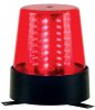
Now! For what I actually need help with, I need to make two of the things in the picture attached. I have the LEDs and some know-how with circuits but I don’t have a circuit diagram to read so can anyone help me? I need a 12 VDC input cycling circuit that runs through 6-8 outputs (being rows of LEDs) at maybe 0.125 seconds each row(?). The LEDs are 30 mA, 3.0 forward voltage. If I need to, I can go to the LED array wizard myself but a little help here would be greatly appreciated.
 

Attachments

  • coolstuff_2121_265843657.jpg
    coolstuff_2121_265843657.jpg
    13.7 KB · Views: 395
how many rows?
what about using a counter circuit?

do you just want it to rotate?
 
i just want it to rotate, id like 8 rows, and i was thinking a 555 timer but i dont know what would be best
 
Hi Mishael,

if I counted correctly the rotating light should consist of 8 columns per 8 LEDs.

Here is a circuit giving you a timing of approximately 125ms for the LED on-time.

Since output '0' is active when the counter is in reset condition the connected LEDs will light steadily when the counter is stopped.

So the entire circuit should be de-energized when no flashing is desired.

Current limiting resistors are calculated for Vf=3V, If=30mA.

Boncuk
 

Attachments

  • BEACON.gif
    BEACON.gif
    21.1 KB · Views: 402
Last edited:
Double post deleted.

Boncuk
 
Last edited:
thank you much boncuk. now i have the problem of wiring that. i can read it just fine but i dont know how to go about connecting those together. especially that IC...would i be able to use copper plates and acid somehow? and if so, how would i do that?
 
Hi Mishael,

I suggest to make several PCBs, one for the control logic and 8 with the LEDs arranged as column.

I will work out a suggestion for the PCBs and post here.

Boncuk
 
Hi Mishael,

here is it.

I added 16 solder pads to connect to the individual LED strips.

The PCB design is purely single sided.

If you want to receive the Eagle files please PM me your email address.

Boncuk
 

Attachments

  • BEACON-BRD.gif
    BEACON-BRD.gif
    53.5 KB · Views: 594
Status
Not open for further replies.

Latest threads

New Articles From Microcontroller Tips

Back
Top