ritayshida
New Member
I have a naïve question about solenoid, but please someone help me out.
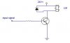
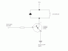
I have a valve 24V DC solenoid. I send a pulse through digital output (5V) to trigger a solenoid, however, solenoid doesn't fire (the valve doesn't open). The voltage I measured was 0.612 V (pulse ON) and 0.0082 V (Pulse OFF). Is this too low?
This is a second solenoid supposedly new. I used the same pulse trigger (voltage I measured was the same) to the first solenoid (24 V DC) and it worked fine. After having used the first one for three years, it had started leaking water even when I didn’t send any pulse to the solenoid. I thought the solenoid was no more usable so that I replaced it to the second one and now it’s not working, either…I do need help.
Thank you in advance,
Rita