Hi there,
Looking for a bit of assistance with error checking a circuit before I attempt build, if anyone can give it a once over to spot any obvious 'mistakes'? I think there will be some, especially regarding component values, but if anyone knows better feel free to let me know.
----
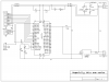
The project is this - to create a simple yet powerful solenoid driver. The solenoid isn't particularly 'hardcore', only draws a few hundred milliamp at 12v, and runs at a low frequency which is very flexible (anything between 100-300hz is good enough).
The control will be all software based, there is no need for inputs as such except for a single adc connected to a seperate external sensor which allows the pic to sense the effect driving the solenoid is having (in this case an external 0-4.6v air pressure sensor).
The unit will have a HD44780 LCD - this is not really for user interface's sake, nor for functionality, I just want to be able to view feedback for when it comes to debugging the firmware as the control routines are going to be tricky and it'd be nice to have some realtime data to work with.
Anyway, I'm not so fussed about the firmware right now, I just want to make sure my circuit is going in the right direction, in particular the N-channel mosfet as this is the bit I found most confusing, and I was never able to simulate it in proteus (could switch a logic mosfet with a 5v battery connected to the gate, but when i replaced it with a pic pin I always got errors regarding timescale too small).
Anyway, this is a fairly complicated circuit for me, anyone fancy a gander?
Finally, I've given values for almost every component. One in particular i'm not sure about is the protection diode across the solenoid. Anyone any idea of what I should look for?
with much appreciation
Dak
Looking for a bit of assistance with error checking a circuit before I attempt build, if anyone can give it a once over to spot any obvious 'mistakes'? I think there will be some, especially regarding component values, but if anyone knows better feel free to let me know.
----
The project is this - to create a simple yet powerful solenoid driver. The solenoid isn't particularly 'hardcore', only draws a few hundred milliamp at 12v, and runs at a low frequency which is very flexible (anything between 100-300hz is good enough).
The control will be all software based, there is no need for inputs as such except for a single adc connected to a seperate external sensor which allows the pic to sense the effect driving the solenoid is having (in this case an external 0-4.6v air pressure sensor).
The unit will have a HD44780 LCD - this is not really for user interface's sake, nor for functionality, I just want to be able to view feedback for when it comes to debugging the firmware as the control routines are going to be tricky and it'd be nice to have some realtime data to work with.
Anyway, I'm not so fussed about the firmware right now, I just want to make sure my circuit is going in the right direction, in particular the N-channel mosfet as this is the bit I found most confusing, and I was never able to simulate it in proteus (could switch a logic mosfet with a 5v battery connected to the gate, but when i replaced it with a pic pin I always got errors regarding timescale too small).
Anyway, this is a fairly complicated circuit for me, anyone fancy a gander?
Finally, I've given values for almost every component. One in particular i'm not sure about is the protection diode across the solenoid. Anyone any idea of what I should look for?
with much appreciation
Dak