Continue to Site

Welcome to our site!

Electro Tech is an online community (with over 170,000 members) who enjoy talking about and building electronic circuits, projects and gadgets. To participate you need to register. Registration is free. Click here to register now.

  • Welcome to our site! Electro Tech is an online community (with over 170,000 members) who enjoy talking about and building electronic circuits, projects and gadgets. To participate you need to register. Registration is free. Click here to register now.

Solar MPPT charger design

Status
Not open for further replies.
Hello everyone. I am designing mppt charge controller. I have been reading on the net about the mppt algorithms and coverter topologies. But I am confused. When you use buck boost converter it will draw maximum power and give output. But I doubt it will take care of battery?
As it will consider battery charging voltage then it will not be able to get maximum power from solar panel (all these are my assumption).
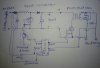
I always have hated buck boost converters. I know much more about push pull converter and implemented the circuits. Can I design MPPT using push pull converter. OR as shown in the attached image.
In the image the first part consist of boost converter which will "take care" of MPP. And the second part consist of Push pull which will "take care" of battery charging. Also I can charge the battery from mains converting 250V AC to 300VDC using rectifier. Is this possible? I would like to implement the circuit shown in the image. Thanks.
 

Attachments

  • 20150920_144505-1.jpg
    20150920_144505-1.jpg
    180.2 KB · Views: 286
Nothing obviously wrong with the schematic, and the overall design will work. but it is less efficient than a true buck-boost circuit that can do all of it in one conversion stage. The advantage to your circuit is that it has the 300 Vdc intermediate point where the AC power line can be switched in. The disadvantage is lower efficiency from the solar panel.

ak
 
How buck boost converter will draw particular value current at particular voltage whicb is our maximum power point and give exactly charging voltage (12-14V) as output? ( I mean I don't get how the three parameters (input vtg and current AND output vtg) are controlled at the same time? )
Also,
Do you have any good websites that explain the converter topologies used for mppt and circuit implementation?
Thanks in advance.
 
To charge a 12V LA Battery, buy a 18-20Voc panel. Make a disconnect circuit that disconnects the panel when the battery voltage reaches 14.5 to 14.7V. Time how long it takes to recharge the battery.

Now convince me that a MPPT controller will shorten the charging time sufficiently to make the MPPT controller worth the trouble...
 
The buck/boost regulator designs I've seen and done are basically output voltage regulators. As the input voltage wanders around, they hold the output voltage a constant. They don't care about the output current until it approaches a self-protecting current limit - then the output voltage sags. For the typical user, the only difference between a buck and a buck/boost is that the input voltage can be lower than the output.

ak
 
Hello MikeMI. In cold temperatures and in cloudy environment the panel produces maximum power. The vtg is typically 18V where battery in discharged condition is at 10.5 V.
A 90W panel in " a very good environment conditions" give you 18V 5A. So you are getting 90W output. When you connect the panel directly to the battery the vtg will be pulled down to something close to 11 V. So your power taken out of panel becomes 11V times 5A wiz equal to 55W. A great loss in power even the panel producing 90W.
 
Hello MikeMI. .... A great loss in power even the panel producing 90W.
I know the theory.

Why not just buy a panel whose intrinsic max power output point occurs when its output voltage is ~12.8V?

Have you ever watched the voltage of a LA battery during charge? It gets to ~12.5V very quickly, then stays between ~12.5V and about 13V for a long time, and then begins climbing quite rapidly after the battery is >90% charged. If the panel matches the battery, going with a MPPT charger gains so little as not to be worth the trouble.
 
Even if we found the panel we will not get output vtg above 10V in summer or when the panel is hot. That's why they produce panels with higher vtgs.

And I have to do this project and submit it in my college. So I don't want to go for any other option instead of making the project.
Thanks.
 
MPPT starts ~80% of Voc (no load) at max solar input ( e.g. 17.1/21.1) and both Voc dropping to 18V and optimum ratio drops with solar input to 70% ratio ( depends on PV chemistry)

Choosing 75% of 18V panel is 13.5 is reasonable with no MPPT . Unless very efficiency regulator or very high power, the gains of MPPT efficiency improvement will tradeoff with losses.

There are two MPPT methods worth using perturbation and observation, (P&O) method and the incremental conductance method (IncCond).

If you know how, it is worth improving energy harvesting efficiency with some effort and complexity over a wide range of solar inputs.
 
Hello AK. Then how the converter will be able to "Hold" MPP of the panel keeping output vtg constant?

You don't track MPP using the regulator output - it is regulated specifically to remove input variations. You track MPP by looking at the output of the panel. I'm not a solar panel wiz, but everything I've seen indicates that output voltage is proportional to output power. Maximize the voltage and you're at MPP. You can add a current monitor and calculate the power, but that is a much more complex approach.

ak
 
Maximize the voltage and you're at MPP.
AK< not so

Maximize V*I and you are at MPP
Did you see what I indicated before?
Tony
 
You don't track MPP using the regulator output - it is regulated specifically to remove input variations.
Negative: When charging a battery with a Solar Panel, the charging voltage is determined by the battery. The MPPT controller becomes an impedance matching device that allows the panel voltage (power output) to be at the optimum point while the battery voltage is whatever the battery voltage naturally is... The dependent variable being controlled by the MPPT regulator is the output voltage of the panel (input to the MPPT).
 
Hang on, now. The question to me was about how it can be possible to use a regulated, constant voltage output to track MPP. My response was that it is not, but that the input voltage to the regulator, coming directly from the solar panel, can be an indication. I also mentioned that a true power calculation is more accurate, but more complex. The response was tuned for someone at the OP's tech level, not y'all.

ak
 
A Photo Voltaic (PV) panel is a variable imperfect current source proportional to solar power input with a limit on short circuit current and no load voltage , both which increases with Solar input (insolarity) although Voc (open circuit) changes very little (10~15%).

Ideally a current source generates most power at maximum voltage, which does not occur, so maximum power generally rises to a maximum sharply as the voltage on the PV drops 15~25% of Voc where the peak drops the most with minimum solar power (insolarity.)

Thus a switched maximum average power point ( MPP) presents a linear impedance using filtered switched pulse regulator, for the 1st stage then draws the maximum power possible without reducing this regulated input voltage. Since solar power is a dynamic input the MPP varies continuously and also the SoC of charge varies continuously.

If the demand power is less than the power available, MPP is almost irrelevant. But more often the demand power is greater than the power available from the PV, so optimizing the PV output MPP maximizes the power transfer to equate the load impedance to the source impedance for a given solar input. This is the maximum power point.

MPPTChart.jpg

SHown for constant solar input. Green is Power, Aqua is current which is constant below 75% of Voc ~77V here
 
So I calculate input power using V and I and then adjust duty so that I get maximum power (P&O method). And then using push pull converter charge a battery.
 
This section covers the theory and operation of "Maximum Power Point Tracking" as used in solar electric charge controllers. AMPPT, or maximum power point tracker is an electronic DC to DC converter that optimizes the match between the solar array (PV panels), and the battery bank or utility grid.
nice topic
 
Status
Not open for further replies.

Latest threads

Back
Top