I suspect the problem is with your first measurement of 6.5 volts and .2 amps. My bet is the 6.5 volts was with no load (Just the output of the solar cell) and the .2 amps was measured by putting the ammeter across the output of the solar panel. Solar panels are funny, the voltage goes down when the load goes up. So what you have is .2 amps at zero volts or 6.5 volts at zero amps. This would make 3.4 volts at .1 amp make some sense. The next problem is the 130ma says the fan has a resistance of about 30 ohms, so the time constant for the 1000 ufd cap is only about 30ms - not long enough for it to get going. If you have lots of caps around you could try adding some more. I have to leave now but getting rid of the scr might also help.
Continue to Site
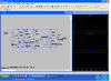
") It might be easier to get another solar panel. But, here is a circuit that uses a logic level MOS FET. This will eliminate the voltage drop across the SCR. It includes a comparator to set the turn on voltage close to the maximum output of the panel and a much larger cap to store some energy to get the fan started. The diode for the voltage reference is not the best but will probably be ok.
It might be easier to get another solar panel. But, here is a circuit that uses a logic level MOS FET. This will eliminate the voltage drop across the SCR. It includes a comparator to set the turn on voltage close to the maximum output of the panel and a much larger cap to store some energy to get the fan started. The diode for the voltage reference is not the best but will probably be ok.