I have a fan which i hooked up to a solar panel. The will start up at 4V and 0.03A on a power supply. My cells are providing ~ 6.5V and 0.2A under my light source but my fan wont start up.
Why? that seems crazy to me.
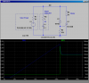
schematic of my simple design is below.
[URL="**broken link removed**
Why? that seems crazy to me.
schematic of my simple design is below.
[URL="**broken link removed**