Continue to Site

Welcome to our site!

Electro Tech is an online community (with over 170,000 members) who enjoy talking about and building electronic circuits, projects and gadgets. To participate you need to register. Registration is free. Click here to register now.

  • Welcome to our site! Electro Tech is an online community (with over 170,000 members) who enjoy talking about and building electronic circuits, projects and gadgets. To participate you need to register. Registration is free. Click here to register now.

Solar Charged Night Led

Status
Not open for further replies.

fritsch

New Member
Hello all,

I'm new to this forums and also new to electronics and I came here to ask for your help on a project of mine. I've never been too much into electronics (still remember some stuff from school years back) and I'd like to learn more about it now.
I wanted to build a small system with a rechargeable battery and a solar panel which would charge the battery during the day and turn on a led during the night.
Since small solar cells and rechargeable "coin like" batteries are damn hard to find around here, I ordered some "solar key chain flashlight" from China.
When they arrived, I opened them and found out it had a good part of my project already done. It consisted in a circuit with 3 parallel LEDs connected to the battery, a switch (between the battery and the LEDs) and the solar cell connected to the battery.
Since my project doesn't include switches, but sunlight incidence, I removed the switch and tied up both "open ends". This made the LEDs stay turned on forever. For the sake of battery saving, I removed 2 of them.
Then, I searched the internet about photoresistors and came up across "LDRs". After studying its mechanics, I ended welding a 5mm one in parallel with the remaining LED, to make the LDR's resistance grow up in the dark and let the current pass through the LED.
It should have worked, but it is not... any clue about something I may be missing here?

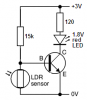
Here's a schematic I made:
**broken link removed**
(yeah, I don't really know how to do this, it's just for clarifying purposes)

Thank you for you attention!

P.s.: excuse me for my english! (portuguese speaker here xD)
 
A solar garden light costs less than 3 dollars.
It has a single 1.2V Ni-Cad rechargeable battery cell, an electronic circuit that steps up the voltage to drive a blue, white or multi-colour LED, a 2V solar panel and an LDR to turn off the LED during daylight.

Your circuit has the LDR shorting the battery and solar panel during daylight. The LDR is supposed to turn on a transistor that turns on the LED when there is no daylight.
 
about the garden light, I know it's a much easier way to accomplish the task (though electronic devices prices in my country are REALLY screwed up. I've seen simple garden lights costing 20 dollars worth), but I'm taking this as a study at the same time, so I can learn something.

anyway, I think I got the idea, it's like the LDR is being 'turned on' during sunlight and using the energy up, right?
can I have some information on how transistors work? (yeah, I don't have a clue)
perhaps the sketch of a schematic?

Thank you!
 
electronic devices prices in my country are REALLY screwed up.
You do not show your country so we don't know.

it's like the LDR is being 'turned on' during sunlight and using the energy up, right?
No.
"Using the energy up" wastes the energy. During sunlight you want most of the sun's energy to charge the battery.
The LDR turns off a transistor that is used as a switch. The transistor then turns off the LED.

A transistor uses a very small input current to control a much larger output current. In a solar garden light the small input current to the transistor is applied by a high value resistor. When sunlight causes the resistance of the LDR to become low then it turns off the transistor that drives the LED.
 
You do not show your country so we don't know.
Oops, I'm sorry about that, forgot to edit my profile. I'm from Brazil!

I've done some research on transistors, but I'm still lost on how should I use it in my project..
I need to find a way to make current flow to the base of the transistor so it can emit current for the LED during night, but the LDR's resistance grows in the dark, so (based on my poor knowledge) I can't use it to turn on the transistor. I know there are LDRs with "inverse effects", which would be perfect for me now, but I just couldn't find them at local stores.

Is it possible to make this with regular LDRs? Or am I dumb enough to be missing some basic stuff here? :S

Thank you!
 
I need to find a way to make current flow to the base of the transistor so it can emit current for the LED during night, but the LDR's resistance grows in the dark, so (based on my poor knowledge) I can't use it to turn on the transistor. I know there are LDRs with "inverse effects", which would be perfect for me now, but I just couldn't find them at local stores.

Is it possible to make this with regular LDRs?
I already told you that a resistor turns on the transistor during the night and the LDR turns off the transistor during the day.
The same LDR can turn on the transistor during the day if you arrange the wiring slightly differently.
 
I understand what you said, but my problem lies on building the circuit. I just can't find a way to wire the transistor and the LDR in the circuit to make it work as intended..
 
The emitter of the NPN transistor is connected to 0V.
The base has a resistor to the positive supply to provide base current to turn on the transistor.
The LDR connects from the base to 0V to turn off the transistor when there is light.
The LED connects from the collector to the positive supply.
 
If you want to do this with a transistor then give this a read scroll down to the Using a transistor switch with sensors section. There are better ways to go about this using a chip but the link shows a transistor example. One problem you face using a transistor is "chatter" as the transition from light to dark or dark to light working with daylight is slow.

Ron
 
Thank you for both answers.

The circuit on Reloadron's link is pretty much the same audioguru has described. Nice link, by the way.
I think I get it now, but there's one problem: my first attempt to make the circuit didn't work because of a short that prevented the battery from being recharged during sunlight (when LDR's resistance is minimum). As far as I can see, this is going to happen in this circuit too.. or not?
 
I've always learned this kind of thing "on the run". I'd rather skip the theory and learn it backwards.
This project is purely experimental :D
 
The LDR turns off the transistor when there is light because it shorts the base to ground, and doesn't short the entire battery and solar panel to ground like in your circuit. The base is provided with a low current by a high value resistor, so when it is shorted by the LDR then its current is still low.
 

Attachments

  • LED and LDR.PNG
    LED and LDR.PNG
    5.7 KB · Views: 303
I've always learned this kind of thing "on the run". I'd rather skip the theory and learn it backwards.
This project is purely experimental :D

except your going that far backwards your blowing stuff up and just wasting your time - your choice mate, I'm no theorist by nature but you can't pull everything out of a hat and expect it to actually work
 
Now if you apply audioguru's circuit along with a simple solar cell to charge your battery you should be fine. Just place a diode between your solar cell(s) and the battery so the battery only charges when the solar cell voltage exceeds the battery voltage and you should be fine.

Ron
 
except your going that far backwards your blowing stuff up and just wasting your time - your choice mate, I'm no theorist by nature but you can't pull everything out of a hat and expect it to actually work

Actually, I've been doing some reading, but I'm not that worried about wasting parts or time, it's just my dumb, osmotic way to learn :p
Thank you for the heads up, anyway.

Reloadron and audioguru, thank you for helping me out, I'm deeply glad!
I'm going to try building a similar circuit with the diode once I visit the electronics shop, then I can post my results.
 
I have 22 solar garden lights.

My city gave away 10 of them for free and the rest I bought on sale at low prices.
They are made in a country that makes cheap junk.

Their old-fashioned and poisonous Ni-Cad battery cells rust away within 1 year so I replace them with modern and North American made stainless steel Ni-MH cells that last "forever". Some of the cheap solar garden lights have steel screws and switches that rust away so I replace them with better ones.

The plastic solar panels are attacked by the sun and do not work after a few months so I polish them with VIM.

Why are the solar garden lights made so cheaply?
 
Status
Not open for further replies.

Latest threads

New Articles From Microcontroller Tips

Back
Top