Continue to Site

Welcome to our site!

Electro Tech is an online community (with over 170,000 members) who enjoy talking about and building electronic circuits, projects and gadgets. To participate you need to register. Registration is free. Click here to register now.

  • Welcome to our site! Electro Tech is an online community (with over 170,000 members) who enjoy talking about and building electronic circuits, projects and gadgets. To participate you need to register. Registration is free. Click here to register now.

Sol Guider using Solar tracker circuit

Status
Not open for further replies.

rsfoto

Member
Hi,

I have read this specific thread

https://www.electro-tech-online.com/threads/simple-solar-tracking-circuit.106625/

with great interest as I am an avid solar photographer using White light and Halpha filters in my Observatory.

My name is Rainer and I live in Mexico.

Now the presented circuit after having read a lot about other solar tracking circuits seems to satisfy my needs with the difference that instead of driving a motor I just need to pull down some TTL outputs to ground in order to activate what we call in astronomy an Auto Guide port of an Equatorial Telescope mount. Normally this ports have 1 common ground and 4 lines which when pulled down to ground activates a corresponding movement of the RA or DEC axis, be it forward or backward.

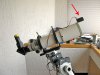
I am talking of German equatorial mounts where normally the only motor in movement is the RA motor following be it the Stars, Moon or Sun. For Autoduigin at night there are many solutions which work perfectly as one takes juts a star and the software calculates its center and when there is a deviation it actvates the corresponding movements.

I have tried similar solutions wioth the Sun building a Sol guider scope but the software is not able to digest the Suns intensity as a stars and it looses the center and so the Autoguding get crazy.

The last mentioned circuit in this thread seem to be interesting but I have a few questions about it.

I do not need to drive directly a motor. I thiink that is the simplest solition by just using tha LM339 comparators output as a switch and close the TTL output.

How accurate is the measuring of the Suns intensity eg how fine do the opposite situated LEDs react to minimal angle changes if the incoming Sun collimated rays do excite the LEDs, in order to create a voltage difference and activate the corresponding comparator output.

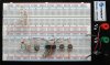
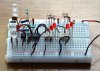
Yesterday I started to experiment with a simple circuit in order to understand how the LM339 works. First by using 2 voltage splitters on theinput of the comparator and then substitutin one pot for a led and turning the remaining pot and I manged to get a ON and OFF switching if an indicator LED connected to the output of the comparator.

I then tried with 2 LEDs but nothing happened as I assumed that every LED reacts different to incoming light and thought it would switch. OK, I have to admit I had no direct SUnlight and maybe there was the problem.

Using just the comparator with a positive V+ input voltage I assume makes the whole tracker more dificult as I need one reference voltage for each lead, so after reading this with the opposite placed LEDs makes it much easier.

Another problem I have is that I have no negative voltage supplies in the observatory. We do work all Positive be it 5V and 12V. I do not see if for my purposes I really need a positive and negative voltage as I just want to open or close the output of the LM339 for switching the TTL connections which in their case activate the motors.

If possible I would like to discuss this here and try to make a suitable circuit for testing it when I have full sun light and the necessary parts.

Sorry for the long introducing message and appreciate any help to get going the project using the presented circuit.

Perhaps my message is a bit confusing :confused:

Thanks and regards Rainer
 
Hi again,

Well after writing my first post I did work out what I thought a working circuit. My goal is to either activate one LED (swtich) or the other LED (switch)

I managed to get it going but not as I expected. Pointing exactly on the Sun both led go OFF. That is OK because that means both sensor leds are producing the same voltage and so 0V ia going to the LM 339.

No when I move the Breadboard in a certain angle one LED goes on which is also OK but after a while the second led also goes on and having the board nearly pointing to the ground they are still both lit. The same happens when I move in the opposite direction but this time with the fact that both LEDs are ON and not only one, I expected to have the opposite one lit but no.

I am clueless

Thanks for any tips. Attached my schematic for testing with LEDs as well as the image of the breadboard set up.
 

Attachments

  • SG-04.png
    SG-04.png
    52.4 KB · Views: 669
  • SG-05.jpg
    SG-05.jpg
    234.4 KB · Views: 1,409
Last edited:
I was just thinking ...

Could the reason be that I am NOT using a negative feed on the GND connection. I am just feeding +12V ...

I bought some LM358N in order to integrate a negative voltage feed ...

Will keep studying this matter ...

Lot of Fun :eek:
 
Perhaps this modification is what you want. Note that I reversed the input connections to U2. I(D3) and I(D4) are the currents through the two output LEDs. Neither LED is on when the light falling on the two sensors is (nearly) equal.

What do want to happen when the two sensors are not illuminated (dark)?
 

Attachments

  • SolarSeeker2.jpg
    SolarSeeker2.jpg
    186.7 KB · Views: 565
Hi Mike,

Thanks a lot. Will try it today.

As this is only to be used when the Sun is shining for making Time lapse movies from the Sun, the device is not going to be used at night or dark, but I think we should define darkness.

For example if a cloud crosses the Sun nothing should happen. The mount should keep moving or tracking as we say at its normal Solar tracking rate and when then the Sun shines again the device should loock onto the Sun as it was doing it before.

From my experience the deviation of tracking maybe for 30 minutes could be around 2 - 3 arcminutes, this depends of the quality of the mount and how well it is polar aligned.

So looking at your new circuit I do not need a negative feed. That is good ;)

Now I will have to see how it reacts and determine the angle difference sensitivity which should be around 15 to 30 arcseconds maximum ~1% in order not to have the Sun dancing to strong in the images, but this again also depends of the focal length of the telescope imaging the Sun.

The Sun apparently varies in Size from 31.5 to 32.5 arcminutes ~ half a degree. The better the raction of the Sol seeker or Sol Guider of course the better the imaging will be.

Again thanks a lot. Will modify the breadboard arrangement and as soon as I have Sun I will test.

What NEVER EVER should happen is to send 2 signal at the same time to the same motor eg. close RA+ and RA- movement at the same time and that is the tiny window I just explained about having the Sun dancing in the movie. :D

The 2 output LEDs are just for testing and they will be exchanged with Optocouplers (for avoiding any ground loop issues) for switching the TTL lines on the mount. BTW I measured the output voltage and current and we are talking of 3.3V against common line and approx 0.3mA.
 
Last edited:
I've always wanted to build a heliostat with computer control. Always thought it would be a fun floating point with trigonometry challenge.
With a heliostat the panels are stationary but you focus tracking mirror(s) at the Sun & panel(s).
 
Perhaps this modification is what you want. Note that I reversed the input connections to U2. I(D3) and I(D4) are the currents through the two output LEDs. Neither LED is on when the light falling on the two sensors is (nearly) equal.

What do want to happen when the two sensors are not illuminated (dark)?

Hi Mike,

EUREKA :D Thank you very very very much. Now it is working as I expected. When the sensor leds are balanced boht test LED are OFF. A movement in one direction switches ON one LED and a movement in the opposite direction switches ON the opposite LED.

But, yes but, but it has nothing to do with the circuit. The prpblem is the incredible Angle sensitivity I have seen with the sensor LEDs I am using.

So now it is time to think how to solve the problem of Light sensing and choosing an angle to detect better the collimated Sun light. This is going to be a mayor task.

Deadband R9 adjustment. As I did no have a 1K pot for the R9 (Deadband) adjustment I used two 3300Ω resistor paralell to a 10K pot which gives me a range from 0Ω to 1400Ω. OK, at 1400Ω the deadband is smaller then at 0Ω. This menas the higher the resistance is here the smaller the angle of the Deadband will be, which helps to define the preaset angle of correction I want to have once I have solved the problem of the lateral light sensitivy and here this means to find out how or what sort of baffling to build.

Nice challenge.

The actual breadboard circuit is using 6 sensor LEDs in a row. I thought using more then one averages the voltage and makes it a bit more stable ?

Another task is now to integrate a calibration method. After setting up the scope and having it exactly in the line of view something like a LED showing the Sol seeker or Guider is calibrated with the scope.

A lot to do but even more fun to build something like this.

Mike, really appreciate your help for this first steps.

regards Rainer

Here you can take a look into my Observatory
https://rainerehlert.com/ObsReal14/ObsReal14-Feb2011-02.jpg
https://rainerehlert.com/ObsReal14/OR14-00.jpg on the left side on the wall on the wooden table is a part of the circuitry for remote control
and this is a control box for a telescope pier https://rainerehlert.com/ObsReal14/Remoto/ControlBoxPier-01.jpg

I have to say that I am NO electric NOR electronic engineer. I am in the Textile industry :eek:

Added a few minutes later. I made a video of the functionality ATTENTION 62MB AVI **broken link removed**
 

Attachments

  • SG-v1.jpg
    SG-v1.jpg
    469.4 KB · Views: 493
Last edited:
Hi,

I now made a remote sensor LED assambly and glued it onto the front of my scope. Look at the images.

I have encountered some issues in regard to the R9 Deadband pot as well as the input of the sensor LEDs. OK, the cable from the sensor LEDs to the board is 5m long but just did that to see what influence it has. The Breadboard is to bulky and that is why id did not mount it in the telescope so far.

The issues when adding the long cable, it is gauge AWG22. The resistance for 1 line at 5m is about 0.1-0.2Ω.

I also had to increase the Capacitor value to 50nF, could not increase it more as I ran out of capacitors :D

Another observation I made is that one comparator swtiches faster the the other, with this I mean one LED shines instantly and the other LED starts to shine as if using a dimmer for lightening it up.

Also I am waiting to get full Sun into the sensor LED assembly and see how it reacts. At the moment I am working with diffuese light but it is operational and it is switching correctly.

In about 2 hours I get the full Sun unless clouds roll in. :confused:

regards Rainer
 

Attachments

  • SG-v1-01.jpg
    SG-v1-01.jpg
    304.8 KB · Views: 468
  • SG-v1-02.jpg
    SG-v1-02.jpg
    104.5 KB · Views: 468
  • SG-v1-03.jpg
    SG-v1-03.jpg
    354 KB · Views: 449
  • SG-v1-04.jpg
    SG-v1-04.jpg
    366.4 KB · Views: 462
Last edited:
It is hard to tell from your photo, but do the optical axes of the two LED diverge by about 20 to 40 degrees? If not, try that. It might give you a smoother crossover in the center...

As long as the wire to the LED sensor array is shielded, 5m shouldn't be a problem.

If you run into a problem where an LED flickers on-off as the sun angle changes, write back, and I will add a little hysteresis to the comparator switching points.
 
I'm thinking that for your application, this is not exactly the right circuit. Wouldn't you be happier with a proportional system that modulates the speed of the tracking motor, rather than a bang-bang on-off system that effectively pulse-width modulates the run time of a motor that either running full speed or not at all? Seems like you could do yours with a motor that never has to reversed, except in the morning when you begin a new observation.

The original circuit was supposed to drive the array from sunrise horizon to sunset horizon, and then automatically seek back to the sunrise horizon the next morning.
 
Dear Mike,

OK. The Sun is shining and as well clouds are passing by ;)

So far what I was able to test it looks promising.

The next step I will make is to solder on a pre drilled phenolic board the circuit as small as possible, perhaps even with already 2 axis sensors LEDs. 2 sensor LED for RA and 2 sensor LED for DEC so the LM339 is fully taken advantage off.

The only issue that worries me is that when the LEDs go into wanting to shine they are flickering. I changed the R9 deadband pot for a 50K and did some adjustments. The flickering of the swirching is still there. As said before I put 50nF instead 10nF, possibly because of the long cable. I will trim this cable too.

There is also a problem with diffuse light ofthe sky when for example a cloud covers the only partially and then the bright part os the Sky is being chase. Here I will experiment with either some tubes or holes in plates in order to really get paralell rays onto the sensor LEDs.

Perhaps if I make the circuit as small as possible and mount it on the Telescope this problems will disappear and I can go back to the recommended values.

Unfortunately this will take some time as I have to leave for a business trip but coming back I will continue working on this.

regards Rainer
 
It is hard to tell from your photo, but do the optical axes of the two LED diverge by about 20 to 40 degrees? If not, try that. It might give you a smoother crossover in the center...

As long as the wire to the LED sensor array is shielded, 5m shouldn't be a problem.

If you run into a problem where an LED flickers on-off as the sun angle changes, write back, and I will add a little hysteresis to the comparator switching points.


I was busy writing an answer and did not see your messages. Sorry. Will take this tips into consideration. No the cable is not shielded but it was only for a test purpose. The final edition will not have such a long cable.

About hysteresis do not worry at the moment, because I did not see that flickering while being the sensor LEDs on the bread board. Please allow me first to make the protoype onto a predrilled phenolic board.

The idea is to integrate eveyting into a closed Box (be it metal or plastic box with a sort of shielding with copper mesh or something) and Piggyback it onto the telescope. I noticed that at the first trials when I did just use one comparator of the 4 and I came near with my finger to the LM339 that he started to play crazy. So for the last tests I connected to ground all unused PINS.

Thanks and regards Rainer
 
Last edited:
I'm thinking that for your application, this is not exactly the right circuit. Wouldn't you be happier with a proportional system that modulates the speed of the tracking motor, rather than a bang-bang on-off system that effectively pulse-width modulates the run time of a motor that either running full speed or not at all? Seems like you could do yours with a motor that never has to reversed, except in the morning when you begin a new observation.

The original circuit was supposed to drive the array from sunrise horizon to sunset horizon, and then automatically seek back to the sunrise horizon the next morning.

Thanks and understand your concerns but we mostly start up our Observatory because we have to open the roof. This are not systems that reside 24/7 outside. So the first slew to the Sun is done by the operator.

The motors of the equatorial mounts do have a special way of being driven. When we speek about autoguiding this means we are addiong or substracting a certain amount of movement.

The basis speed, what we call tracking, is 1x which equals to a speed of 15 arcseconds (spatial distance) per second (time) The Sun and Moon speeds are bit slower or faster but not that much.

The so called Autoguider port speed is adjustable between 0.2x to 1.0x (remember "x" is 15 arcseconds per second) So we can not talk here from a huge acceleration or decelaration of the motors. Those are small speed additions or substractions which do not harm the motors.

Thanks and regards Rainer
 
Hi Mike,

As said I just cut the wire down to a short length in order to be able to play a bit more and the flickering of the test LEDs disappeared.

So as the sensor LEDs will be placed on the board too there will be no problem with this.

Now I will start tp play with different angle positions of the Sensor LEDs to see what diferences I get.

Question: Would it be advisable to use 2 or 3 leds in order to get a less nervous voltage from the sensors or wont whis change anything. I guess the capacitor already in the circuit dampens this ... I assume the resistor in paralell is for killing the current ¿?

Question: How does the R) Deadband influence this. Higher value = bigger angle difference ?

I am trying also with a baffle inbetween both sensor LEDs. Unfortunately I do not know the angle of the LEDs. THe specs are Green water clear 3.2V 100mA.

Sorry for so much questions :eek:
 
Hi,

OK, after coming back from my trip to Old Europe I was able to continue with my project.

I breadboarded now EAST-WEST and NORTH-SOUTH axis and just tested it. It works :D

Now I have to solder the circuit on a phenolic board. Now I still have to integrate an RJ12 connector which would be the counterpart to the Autoguide port of the Equatorial mount. Fiddle out which switch from the Optocoupler moves East West North South. I guess Trial & Error ...

The most difficult part is now how to arrange the sensor LEDs so the dead angle of movement is acceptable.

My goal is to achieve a reaction when the angle changes by ~ 0.001° degrees :eek: I know some of you will declare me insane :D

I already made a test which looks very promising and that is to place a hole over 2 of the sensor LEDs covering a certain part, perhaps 40%. Look at the attached image. When the Sun shines absolutely parallel into the hole both LEDs have the same voltage and nothing moves. If the Sun shines at a very slight angle the change in coverage is immediate as I get an Ellipse and so the iluminated surface with a very small angle changes quite much from sensor LED to sensor LED.

OK, this will be a lot of R&D as well as Trial & Error :D

Thanks for reading and looking at the images

regards Rainer
 

Attachments

  • SG-v1,1-1.png
    SG-v1,1-1.png
    43 KB · Views: 467
  • SG-v1,1-2.jpg
    SG-v1,1-2.jpg
    2.4 MB · Views: 480
  • SG-v1-sensor.jpg
    SG-v1-sensor.jpg
    196.2 KB · Views: 446
It's more energy efficient to have a less-sensitive sensor, and hysteresis in your comparator. That way the motor will only run once (for a few seconds) every 5 minutes or so, and use no power for the rest of the 5 minutes.

The last thing you want is sensitive detection, that thing will be twitching around all day and using up power, wearing out the mechanicals etc.

Hi,

Thanks for the answer but the intention here is NOT to drive a motor constantly with this circuit.

This development is what I call an Autoguider which in terms of amateur astronomy just sends short correcting impulses which make already running motors just speed up or speed down the tracking motors in order to maintain the Sun in the telescope center.

The output of the Optocoupler will be connected to the so called Guide port. The Guide port has 4 lines with an output of 3.2V and delivers only 0.3mA. When you close the circuit of one of this 4 lines against a common ground 5th line the corresponding motor speeds up or down according which line is closed. This sort of Guide port corresponds to a so called ST-4 standard which is a common standard in the amateur and we are talking from a TTL switching.

The circuit draws at maximum 50mA druing operation when all 4 test diodes are working.

**broken link removed**

regards Rainer
 
Thanks for explaining that, I missed that because I just skimmed your first post sorry. :)

If you are wanting to do accurate telescope tracking, I would avoid "speeding up corrections" etc completely, and just lock the motor speed to a xtal oscillator. Since the rotation speed of the sun relative to the earth is known, you can just run the motor at the perfect speed. That also eliminates errors from your sensors, as it does not need sensors.

I recently did a project just like that, using a DC motor;
https://romanblack.com/onesec/DCmotor_xtal.htm

What type of motor do you have on your telescope? Maybe you could use that system and do away with sensors, sensor errors, sensor cleaning etc.

No problem. I am talking of the newest iOptron ZEQ25 GT.

So the mount has already Solar tracking rate incorporated but as you know that are nit that accurate to keep the Sun for hours in the center if the imaging camera, so onw has to do minor corrections.

This corrections can be adjsuted in the menu of the Equatorial mount by adding a so called x factor as guide rate. This mount is adjustabl from adding of substracting a speed of 0.1X to 1.0X. X means 15 arseconds of spatial distance in 1 second of time. So if I adjust 1.0X in the autoguide rate and I leave the contact closed for 1 second my mount witll move at a speed of 2x in stead of 1x which is the normal tracking rate or viceversa it would substract 1x from 1x and the motor would come a still stand.

That is why I am ainimg for a very short time of corrections but quite continuous. This does not affect the motors as we do it normally all night long when imaging Deep Space Objects :) using a star on which we hang on and measure the movement of this star and chase this star. IN this case I would chase the Sun adn tell the EQ where the Sun is trying to escape too.
 
Their solar tracking rate might not be that accurate, but mine is. ;)

Even driven from a xtal you can tune it to one PPM accuracy, which is about "X" / 1000000 per adjustment step. Alternatively running from a GPS lock it gets about a hundred times more accurate than that!

Anyway if you prefer a closed loop system to really accurate clockwork tracking that's up to you. In that case I think sensor design, reliability and cleaning will be critical. :)
 
Status
Not open for further replies.

New Articles From Microcontroller Tips

Back
Top