camerart
Well-Known Member
Hi,
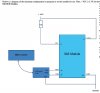
I would like to make a SCR with a DRA818U radio module. See attached PDF.
I want to control it with a PIC, I have 16F648A PICs which may work.
I will need a program to control it, any ideas welcome.
It should be able to send and receive voice or data, so should be interesting.
I WILL ADD AND CHANGE FILES HERE, AS THEY DEVELOP.
EDIT: Here are translations from http://599.cz/view.php?cisloclanku=2015052801 website by Jarda ok1hdu.
As the ATMEGA48 isn't fully supported, I am hoping to use an 18F2431PIC instead (both 28 pin) It looks as though I will need to make an adaptor, as it looks as though they can't be used pin for pin. I am trying to convert EricG's 18F4520 program onto it. So far I've changed the LCD connections to suit.
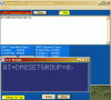
Apart from the above complete radio, one of my interests is sending and receiving data. I think the DRA818 can be programmed by a terminal (e,g, Putty) and simply send or receive data to or from a base receiver, for e,g, balloon tracking etc. I'm going to try this first
Camerart.
I would like to make a SCR with a DRA818U radio module. See attached PDF.
I want to control it with a PIC, I have 16F648A PICs which may work.
I will need a program to control it, any ideas welcome.
It should be able to send and receive voice or data, so should be interesting.
I WILL ADD AND CHANGE FILES HERE, AS THEY DEVELOP.
EDIT: Here are translations from http://599.cz/view.php?cisloclanku=2015052801 website by Jarda ok1hdu.
As the ATMEGA48 isn't fully supported, I am hoping to use an 18F2431PIC instead (both 28 pin) It looks as though I will need to make an adaptor, as it looks as though they can't be used pin for pin. I am trying to convert EricG's 18F4520 program onto it. So far I've changed the LCD connections to suit.
Apart from the above complete radio, one of my interests is sending and receiving data. I think the DRA818 can be programmed by a terminal (e,g, Putty) and simply send or receive data to or from a base receiver, for e,g, balloon tracking etc. I'm going to try this first
Camerart.
Attachments
-
DRA818U.pdf387.5 KB · Views: 475
-
SCR.txt18.8 KB · Views: 425
-
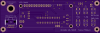
 201505281938_UHF_FM_w.png36.4 KB · Views: 538
 -
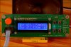
 201505281939_IMG_9486_w.jpg188.8 KB · Views: 483
 -
 201505281947_Panel_F.png35.4 KB · Views: 447
 -
 201505281948_Panel_B.png34.5 KB · Views: 490
 -
 201505281951_IMG_9483_w.jpg157.8 KB · Views: 448
 -
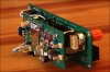 201505281952_IMG_9488_w.jpg127.8 KB · Views: 516
 -
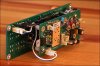 201505281954_IMG_9489_w.jpg153.3 KB · Views: 484
 -
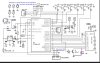 Schematic.jpg190.6 KB · Views: 509
 -
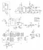 Schematic with coils.jpg149.3 KB · Views: 550
 -
DRA818U 18F2431 INT20 300816 0900.txt2.7 KB · Views: 408
Last edited:
")