Continue to Site

Welcome to our site!

Electro Tech is an online community (with over 170,000 members) who enjoy talking about and building electronic circuits, projects and gadgets. To participate you need to register. Registration is free. Click here to register now.

  • Welcome to our site! Electro Tech is an online community (with over 170,000 members) who enjoy talking about and building electronic circuits, projects and gadgets. To participate you need to register. Registration is free. Click here to register now.

Soft start circuit problem

Status
Not open for further replies.

vsaar

New Member
Hi,

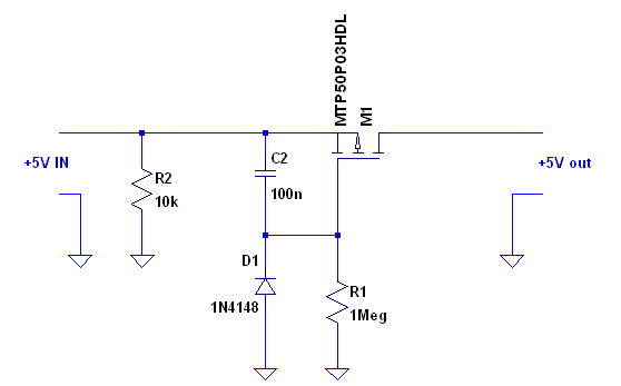
I'm testing a soft start circuit which is posted here earlier: (having SI4465DY in place of M1)
soft-start-sch-png.34784

I'm having problems with the inrush current of 5V step-up converter ordered from Pololu.com, which is only drawing huge amounts of current and is unable to start properly because of Vin dropping too much in this situation. I'm building a Geiger dosimeter which will be powered by 2 AA NiMH cells, which means Vin to be no more than 2.4V when they are nearly empty, and will drop more when taking current from them. Even with my power supply it's a little shaky to start properly, unless I give it at least 3 volts. I wanted to use 4 AA cells which would help a lot, but couldn't find any enclosure with 4 AA compartment suitable for this project so I have to live with 2 cells.

With that soft-start circuit I'm able to start my project having Vin as low as 2.2V (the step-up converter is in the left side of that picture), but there's still an another problem. D1 and R2 are meant to rapidly discharge C2 so the soft start is immediately ready to work again and it works, however any capacitors in the device itself (in the right side of that picture) will leak back thru the body diode of M1 and therefore the soft-start is not "reloaded" before those other caps are also discharged. That can take up to several seconds. In the event of main power switch contact bouncing, it's very possible that the step-up converter will again go nuts because C2 didn't have time to discharge, and will blow the fuse or something else.

Anyone having ideas how to get the C2 rapidly discharged when putting power off, regardless of other caps there? Putting a diode after M1 is no-go because of too much voltage loss. My project will use up to 50 mA of current, but typically only 15 - 25 mA.
 
I think I would try a big cap across the batteries. Say 10 or 15,000 Ufd. Might hold the voltage up long enough to get it started. Either that or get one of the regulators that will start at .5 volts.
 
Hi,

I like the large cap idea, if you have the room that will probably do it.

If not, then to discharge a small cap like that a small transistor is normally used.

One idea is to raise the 10k to 100k, then instead of disconnecting the battery to switch off, just energize another transistor that shorts out the cap. That will also turn off the bigger mosfet and then the battery power consumption will go way way down into the years of operation even though the battery will be connected to the circuit 24/7.

Another idea is to use a single pole double throw switch for the power switch. The third terminal is connected to the mosfet gate, with the common terminal to the input +5v line. When the switch it turned "off", the secondary contacts short out the cap. When the switch is turned on again, the cap is released to allow charging again.
 
I've tested with a 1mF cap which is largest what I have now, but it didn't help much. Any bigger cap wouldn't fit into the enclosure anyway.

The main power switch is actually an another 1.8V rated P-mosfet which will be opened by grounding its gate with a pushbutton, and then the microcontroller holds it open until shut down by software. This however makes the inrush current problem even worse, because the Vin drop also gets the fet out of saturation (not much room from 2.3V to that), which then will produce more drop. So I think the soft start would be the best approach, and maybe I should make some debouncing to the power button.

Here is my schematic so far: **broken link removed**
 
Can you use the softstart circuit as the main power switch as MrAl suggested? You could use another P-MOSFET to short across C2. Grounding its gate will turn the power off (could be a 1 meghom resistor). Connecting its gate to V+ (by the pushbutton) will allow C2 to charge and slowly turn on M1. The 1 megohm at M1's gate will be a negligible load on the battery (.02AH/year when the power is off).
 
Looking at your 3 page schematic:
You want to charge C3 from 0 to 5 volts with the energy stored in C2 and (C1 through Q1).
>Try making C2 smaller. Maybe make C2 larger.

I see that some voltage from C3 runs back through Q4 and charges C11. That kills you RC delay.
>You have a computer. Drive Q4 by the computer. Make the delay in software.
 
Hi again,

What is R12 doing there, or should i say, what caused the inclusion of R12?
It looks like R12 will hold the MOSFET on longer.

Pretty neat project.
 
Can you use the softstart circuit as the main power switch as MrAl suggested? You could use another P-MOSFET to short across C2. Grounding its gate will turn the power off (could be a 1 meghom resistor). Connecting its gate to V+ (by the pushbutton) will allow C2 to charge and slowly turn on M1. The 1 megohm at M1's gate will be a negligible load on the battery (.02AH/year when the power is off).

This is one possibility and I need to think about it. In that case the step-up converter would be always on, and I measured it taking 0.25 mA without load. That makes about 6 mAh per day, which is probably still less than the self discharge rate of NiMH cells.

Looking at your 3 page schematic:
You want to charge C3 from 0 to 5 volts with the energy stored in C2 and (C1 through Q1).
>Try making C2 smaller. Maybe make C2 larger.

I see that some voltage from C3 runs back through Q4 and charges C11. That kills you RC delay.
>You have a computer. Drive Q4 by the computer. Make the delay in software.

I moved C1 to be before Q1 so it would be already charged when switching the power, otherwise it would also take current when charging and making voltage drop worse.

Yes, that is the problem of that soft start as I mentioned earlier.

About driving Q4 by a microcontroller, the AVR is placed after soft start so it needs power first before it can do anything. :) But as you said that, I got an idea to put another smaller AVR between the converter and Q4 to drive it up by fast PWM (with small capacitor). The power on button would be then routed to that smaller AVR to make it wake up from sleep and drive Q4 slowly up, and then the same button could be used as an Off button to shut the thing off. Then there may be no need to discharge caps after shutdown. Also Q1 and those other things near it could be removed so the step-up converter will be always on, but the power consumption shouldn't be too bad when powered off. No more problems with pushbutton bouncing either, as the AVR will do its job after getting one signal.

Hi again,

What is R12 doing there, or should i say, what caused the inclusion of R12?
It looks like R12 will hold the MOSFET on longer.

Pretty neat project.

Q4 is Vgs 1.8V rated mosfet, so there's no need to pull the gate all the way from 5V to GND. I added R12 so the gate will be pulled down to about 2V instead of 0V, so at shutdown it would be faster to discharge C11. I was in a hurry when thinking that and I'm not sure if it was so good idea or not. With a normal logic-level mosfet R12 should not be there.

----

Thank you folks for your thoughts, I have now lots of thinking to do. When starting this project at February I surely didn't think the power supply would be the toughest area. My earlier projects are powered by wall warts, and it's just so easy to use good old 78xx regulators when you don't have to worry much about power consumption. Before this I built few digital clocks, and there's also some pictures of them at here: **broken link removed**
 
Hi again,

I see you like LED displays too. I liked LCD displays when they first came out but quickly tired of them. I like 7 segment displays because they are lit up at night and look much nicer than LCD.

Another simple idea is to use a transistor as a current amplifier, which then makes a capacitor on the base look bigger. This allows a much smaller cap like 0.01uf and that should discharge very quickly.
There are several possible configurations, i'll describe one.
A PNP transistor with emitter on the +5v input (first smaller schematic). Collector goes to MOSFET gate. Capacitor goes from transistor base to ground, say 0.01uf, possibly with small resistor in series. Diode from base to +5v input, with cathode to +5v input and anode to transistor base.
When the +5v first appears during turn on, the cap conducts and drives the base through the emitter, the transistor turns on, keeps the MOSFET gate high. As time passes the cap charges and that means the transistor stops conducting hard, so the MOSFET turns on.
When the +5v input goes toward ground, the capacitor discharges into the +5v input line.
Almost like before except now we use a 0.01uf cap which is 10 time smaller than 0.1uf.
 
Something doesn't seem right. Your regulator should start with 0.5 volts according to the spec sheet. It may still be inrush on your dead batteries I suppose. I think I would still try propping up the batteries. You could change the 220 @ 16 vdc across the batteries with a 1000 Ufd @ 6.3 vdc (same size) and try removing the 220 at the output that must be charged at power up with something smaller.

Edit, Just realized that's the same thing Ron S. posted.
 
Last edited:
I have solved the problem now. :) I put in an ATtiny85V which is powered directly from battery voltage (will work down to 1.8V). By pushing the button, it will wake up from sleep mode and switches the 5V step-up converter on without any load in output, and then by using PWM it drives the main circuit on slowly (about 200 ms). Ta-daa: no more stuck with inrush current! Probably I could make that way faster than 200 ms without problems. It's also measuring the battery voltage and will not start the main circuit if the batteries are too empty, and will also monitor the voltage during soft start to detect possible inrush 'deadlock' and shutting down immediately if needed.

All this worked nicely in breadboard (quite a mess), so I'm pretty sure it will not be worse when soldered into perfboard. I can only wonder how many people have found those step-up converters to be useless because of inrush current problems. I was about to be one of them, until I found the idea of soft start and got it to work properly.

I have updated the schematic which I think will be final. I have not yet built the perfboard though, but will add some more pictures later.
**broken link removed**
 
Status
Not open for further replies.

New Articles From Microcontroller Tips

Back
Top