Continue to Site

Welcome to our site!

Electro Tech is an online community (with over 170,000 members) who enjoy talking about and building electronic circuits, projects and gadgets. To participate you need to register. Registration is free. Click here to register now.

  • Welcome to our site! Electro Tech is an online community (with over 170,000 members) who enjoy talking about and building electronic circuits, projects and gadgets. To participate you need to register. Registration is free. Click here to register now.

SMPS: Output capacitor calculation?

Status
Not open for further replies.

MUM

New Member
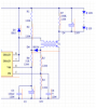
trying to design a SMPS with constant current output.

input:
230Vac, 50Hz
Output:
constant current 150mA , 130V (Max Po=19.5W)
SMPS frequency is 60KHz
Ripple current ratio: 30%

I am a bit confused between the relationship of ripple voltage, ripple current and ripple factor.
1) how to calculate the output capacitor value to achieve the above ripple current ratio.
2) how to calculate the output capacitor value if I already have an inductor L in series (like a LC filter)
 
Obviously the higher value you use will produce a better result.
Use the largest capacitor you can fit on the board. Anything above 100u will be ok.
 
Tks for the Info, but can i have the calculation method of the optimum value, based on the allowable ripple current value given.

The space is very limited, even a 100uF/150V is difficult to be placed, so I was looking for an option of LC filter instead of just a capacitor. But for this i need the calculation method details.
 
We should know what type of SMPS.
>A buck PWM, the inductor should have continuous current. so the cap can be smaller.
>A flyback will have current flow only part of the time. so the cap must fill in. bigger cap.

>Duty cycle also makes a difference. How long must the load be supported by just the cap.

60khz = 16uS at 50% duty cycle = 8uS
I think you are designing a LED power supply. If so then your load is complicated. It is not a resistor.
>You want 30% ripple (or less)
>Question: At what voltage will the LED draw 15% less current? and at what voltage will the LED draw +15% current?
>The voltage needs to stay in between these two voltages.
>At 150mA and (the time your PWM is NOT outputting power) and the ripple voltage = what capacitor?
>150mA 8uS 30 volts = capacitor? Just guessing at 8uS and 30V
>All this is for square wave current and you probably have a current ramp so double the capacitor.

Hope this helps.
 
Tks Ron for the detailed info.

I think I missed out one important point that this is an APFC controlled SMPS, so I think the frequency we have to consider is 50Hz mains frequency and not the SMPS operating frequency. Please correct me if I am wrong.

Yes it is for LED load
VfLED @ +15%Io = 134V
VfLED @ -15%Io = 128V

By the way the ton= 9us, toff=8us

So what formula i should take to calculate the Co?
And will the T1 (1mH primary inductance) act as a 'L' filter? if yes, then what should be the Co value?

Reference Schematic of the output section.
upload_2016-3-1_11-44-0.png
 

Attachments

  • upload_2016-3-1_11-43-48.png
    upload_2016-3-1_11-43-48.png
    39.7 KB · Views: 162
I think the frequency we have to consider is 50Hz
Is your design "PFC" Power Factor Correctored"?
>If not there is a large capacitor and full wave diodes. This cap holds up the supply during the 50hz time. So the output cal is for 60khz.
>If yes to PFC then we are talking 50hz. We must hold up for the time related to 50hz.
And will the T1 (1mH primary inductance) act as a 'L' filter?
What is the current in the "switch"?
>230Vac X 1.414=325Vdc (about)
>The switch is on for 9uS and of for 8uS. (seems right for 325Vin and 150Vout buck down)
>>175V for 9uS and 1mH So 1.5A is the change in current. Well that is much higher than the 150mA. Why? Maybe PFC?
>>150V for 8uS and 1mH So 1.2A for the diode. (these are approximate)
These peak currents seem high.
>Is the supply continuous or discontinuous?
I need to see your total schematic.
 
This is the complete schematic
upload_2016-3-1_13-42-12.png


Since the SMPS was for range of input voltage , so i had given the values for in-between input voltage

Lowest input Vac will be ~150Vac, so following are the values at this lowest input:-
Ton=9.4us
Toff=6us

@230Vac input the values are as below:-
Ton=3.2us
Toff=4.8us
 
What is U1?
Looks like PFC. So you need the LEDs during the times when 50hz is not on.
 
Yes, as already informed it is Active PFC circuit, so i need a calculation formula for the output capacitor value.
Also whether the primary inductor will act as a 'L' filter?
 
For some confidential reasons can't give the part number, hope you understand.

the transformer is acting as a feedback and also as a sustained power(very small) to the U1.
The inductance is calculated based on the formula for U1 to set the desired operating frequency.
 
For some confidential reasons can't give the part number, hope you understand.
LOL ok
So lets forget the IC and most of the circuit.
We know that power is coming in at 50hz. (actually 100hz)
The PFC out puts half sign wave current at 100hz.
For simplicity lets pretend there is a full wave bridge and Cout and the load and that all.
The inductor is small at 100hz. It is large at 60khz. (not much filtering at 100hz)
You should be able to find the formula for Cout for a full wave bridge.
Cout must hold up the load for about 1/100hz. 10mS
You have a cap at +Vpeak and it discharged at 150mA to -Vpeak in 10mS, what cap value?
The cap could be a little smaller but this will get you close.
 
Tks Ron

I was actually a bit confused with the 'L' filter because of the dual frequency component. And this was because of the PFC
Your explanation was in very simple words and now I have understood the point clearly.
 
Status
Not open for further replies.

Latest threads

New Articles From Microcontroller Tips

Back
Top