Continue to Site

Welcome to our site!

Electro Tech is an online community (with over 170,000 members) who enjoy talking about and building electronic circuits, projects and gadgets. To participate you need to register. Registration is free. Click here to register now.

  • Welcome to our site! Electro Tech is an online community (with over 170,000 members) who enjoy talking about and building electronic circuits, projects and gadgets. To participate you need to register. Registration is free. Click here to register now.

Smooth PWM current control of a Maxon DC Motor

Status
Not open for further replies.

rdleslie

New Member
Hey Guys,

I found this forum searching for answers regarding the design of H-bridge circuits for DC motor control.

I've hit a snag with my design (which is my 1st ever), and in my reading I've found that many of you seem to have much experience with DC motor controls. Any help would be much appreciated!

I have developed a board with the purpose of controlling the current applied to three Maxon F2260 motors (889 winding), link to datasheet below

https://irtfweb.ifa.hawaii.edu/~tcs3/tcs3/vendor_info/Maxon/F2260%20Motor.pdf

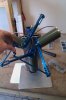
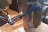
The main performance criteria for my controller is to apply smooth ripple free current to the motor. The motor is coupled to a robot that a user interacts with by backdriving the robot.. and I want the motor to have no feeling besides the intended torque signal.

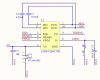
Im using dsPIC33f microcontrollers to drive each of the three axis.. and have the PWM set to 20KHz. These each in-turn are connected to LMD18200T H-Bridge drivers.

I've noticed two things in this design.. not sure if this is typical or not

1) That I have a huge deadband for PWM, where I assumed the voltage (or current) across my motor would be linear with the duty cycle. I did a graph of the motor current as a function of my PWM duty cycle.. you will see several lines representing my testing at different shaft angles, and for each of my 3 motors.

(image attached)

So for my controller I've had to fit an equation to this data such that I can somewhat accurately command current to my motor.

2) The continuous current rating for my motor is 1.69 amps, which is well below the 3A continuous rating for H-bridge driver. At about half of this current value.. around 0.8A the motor begins to feel gritty when you backdrive the shaft... This is highly undesirable for my design.. since the whole point of my robot is to transmit smooth torque through the robotic linkage to a human hand.

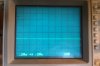
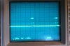
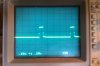
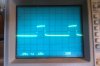
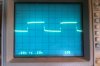
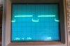
I tried hooking up my oscilloscope over the motor terminals to see what the actual signal was doing... and this ended up actually changing the performance of my circuit.. and something didnt seem right.. so I pulled the scope of in fear that I might damage it..

anyways.. this post is getting long.. any help would be much appreciated..

cheers,
 

Attachments

  • Isense.jpg
    Isense.jpg
    49.3 KB · Views: 925
What kind of bootstrap capacitors you have connected to the LMD18200T (Bootstrap 1 and Bootstrap 2)?
Should be a 10 nF ceramic rated at about 15 volts or higher. Without the bootstrap capacitors, the h-bridge is not able to switch faster than 1kHz.

Did you have the motors stalled when you measured the currents?
The motor could feel "gritty" because of the current limit of the h-bridge is kicking in. What is your supply voltage?

The electrical time constant of your motor is about 375 microseconds. With that time constant I would use PWM frequencies above 30 kHz. Maybe even 40...60 kHz if you can get enough resolution from your microcontroller.
Some Maxon controllers use choke inductors in series with the motor. The motors have such low inductance that external chokes are needed to smooth out the ripple current.

I think that the nonlinearity of your current/duty-cycle curve comes from the low inductance of the motor winding and the low pwm-frequency. The current ripple is so high (in amplitude) that it gets cut off at low currents (i.e. it cannot go negative). Similar to a buck converter operating in a discontinuous mode.

Discontinuous mode:
https://upload.wikimedia.org/wikipedia/commons/c/c6/Buck_chronogram_discontinuous.png

Continuous mode:
https://upload.wikimedia.org/wikipedia/commons/6/63/Buck_chronogram.png

If you use the LMD18200T in the "Simple, locked anti-phase PWM"-mode you will probably get the linear action (near zero volts/current) you are looking for. Other solutions would be increasing the pwm frequency and/or increasing the inductance (adding a choke coil).

You can find more about the bootstrap capacitor, pwm-modes etc. from the LMD18200 datasheet https://www.electro-tech-online.com/custompdfs/2010/09/LMD18200.pdf


You can calculate the ripple current with the formula (approximation):

Iripple = Vcc / (2 * Fpwm * (Lm + Lc))

Where:
Iripple = ripple current amplitude.
Vcc = supply voltage.
Fpwm = pwm frequency.
Lm = motor inductance.
Lc = choke inductance.

Assuming you have 48V supply voltage, the ripple current of your application is about 0.6A. The minimum average current would then be about 0.3A for the ripple current to be continuous.
I think the numbers and your graph match close enough (the discontinuous corner of your graph is roughly at 0.3A). If you are using the "Sign/magnitude PWM"-mode, the ripple current is probably a little bit smaller.
 
Last edited:
It would take a "differential input" (two probes, Chan. A and B set to same gain, Vertical display set to A-B) to look at the motor voltage. I'll bet you hooked the scope probe ground clip to one side of the H-Bridge. You are lucky you didn't blow up one side of the bridge...
 
Some scope plots of my PWM

It would take a "differential input" (two probes, Chan. A and B set to same gain, Vertical display set to A-B) to look at the motor voltage. I'll bet you hooked the scope probe ground clip to one side of the H-Bridge. You are lucky you didn't blow up one side of the bridge...

Hey Mike,

You are correct.. and that makes total sense now! Damn.. I am lucky that everything is still working as it did.. I guess in essence what I was doing is hooking one of my H-bridge outputs to ground.. which when driven to my 18.3V Vs.. would draw a crap load of current through the scope!!

I think what happened is the LM18200t has over-current protection for its switches, I think that saved me. My scope is 10A fused, and my powersupply cannot out put more than 10A as it is.


Anyways, with your advice I PROPERLY hooked up my scope and found the following results..

Im using 20Khz pwm with an 18.3V supply, and each vertical division represents 10V on my scope.

I've shown plots for pwm commands of: 0,250,500,1000,2000,3000 and 4000.. where 4000 is full duty cycle.

at this frequency I have a pwm resolution of 4000 in forward, and 4000 in reverse.
 

Attachments

  • IMAG0140.jpg
    IMAG0140.jpg
    1.2 MB · Views: 599
  • IMAG0141.jpg
    IMAG0141.jpg
    1.1 MB · Views: 514
  • IMAG0142.jpg
    IMAG0142.jpg
    1.1 MB · Views: 503
  • IMAG0143.jpg
    IMAG0143.jpg
    1.1 MB · Views: 525
  • IMAG0144.jpg
    IMAG0144.jpg
    1.1 MB · Views: 530
  • IMAG0145.jpg
    IMAG0145.jpg
    1.2 MB · Views: 507
  • IMAG0146.jpg
    IMAG0146.jpg
    1.1 MB · Views: 487
Sorry MisterT,

I replyed to you yesterday, but for some reason my response didnt get posted.. I'll try again.

I am using 10nF bootstraps.. I think they're 50V rated.

I also did have the motors stalled; I guess I should have mentioned that my supply is 18.3V with a max output of 10A. I think the max current my motor can draw before it saturates my supply voltage is around 3.4 amps. They say in the LMD datasheet that it can source 3A continuously.. I've actually noticed that the LMD18200's are not changing temp.

I did a bit of reading regarding elec time constants and the Buck converter operating modes, as you posted. I know that at 20KHz my period is 50us, and according to wiki's page on RL circuits it takes 5 of the R/L electical time constants (375us) for my circuit to reach its steady state..

so If I switch it slower, basically the change in current will be more drastic right?

I am controlling the LMD in the sign/magnitude method, and actually fixed one of the errors I had earlier with the non-linear pwm response; turns out I had a silly bug in my code and wasn't talking to the LMD properly!! fixed it and now all is well.

Is your ripple calculation only valid for locked anti-phase PWM? I did find a doc put out by maxon called "PWM Technical Info" that is rich with electrical formulas regarding pwm response.

Anyways, I'm still having issues with the grittyness... which isnt terribly good for a haptic device! I'm gonna keep at it!

Thanks a million for your help!
 
Maxon document regarding ripple calculations and pwm modes
 

Attachments

  • PWM technical information.pdf
    106.7 KB · Views: 1,374
I just coded a simple PV controller on one axis of my robot.. and I am actually getting very tight control.. so it appears the pwm amplifier can at least work well in a position control context. I was able to have my motor track a sine wave command up to 20Hz, and the motor is directly connected to a first link of a robot..

Alas... still feel the grit though when Im backdriving the motor by hand..

Here are some images of the actual haptic device.
 

Attachments

  • IMAG0126.jpg
    IMAG0126.jpg
    1 MB · Views: 659
  • IMAG0147.jpg
    IMAG0147.jpg
    1.6 MB · Views: 579
I did a bit of reading regarding elec time constants and the Buck converter operating modes, as you posted. I know that at 20KHz my period is 50us, and according to wiki's page on RL circuits it takes 5 of the R/L electical time constants (375us) for my circuit to reach its steady state..

Apparently I made some mistakes in my calculations. With the 375us electrical time constant the 20kHz PWM should be high enough.

The pdf you found ("PWM-Scheme and Current ripple of Switching Power Amplifiers") looks very good. It explains the different PWM-schemes and shows how to calculate the ripple current.

The formula I used to calculate the ripple current is the same presented in the maxon technical paper for 2 stage PWM (which is the same as "locked anti-phase PWM").

I did the calculation based on the complimentary scheme, which is how I am controlling the switches. I found that for as low as 20KHz the ripple current was well within my tolerance.

MrT, do you design embedded control systems for a living?

Ever had a power supply come into play as an issue?

I ask because I am now starting to wonder if my powersupply is causing the gritty feeling. Maybe as it starts to source more current it can ripple a little more.. and the ripples become precievable at the motor.

I dunno, just speculating.. I could try and hook another supply up and try it out.
 
I'm still finishing my studies (automation and systems technology and mechatronics), but I also work as a research assistant and course assistant at the university.

Hard to say what is causing the "gritty feeling". Gritty does not sound like a 20kHz vibration caused by the current ripple.

I hope you have some capacitors close to the h-bridge supply input for handling current spikes. But I don't think the power supply is causing the gritty action.

Maybe the gritty feeling comes from your control algorithm. It would be very useful to log all the data for analysis. If you could log and plot the position sensor reading, the controller output, the position setpoint, the position error etc.. What is the resolution of your position sensor (number of counts, if its optical encoder; ADC resolution if its analog sensor). What is the frequency of your control algorithm? What kind of control algorithm you have implemented?
 
Last edited:
Awesome, so robotics and control must be an interest of yours I would assume!

I've done robotic design from the mechanical side of things; just now venturing into the control and electrical aspects of it.

When I close the loop on the motor position (using a PD controller) I'm actually seeing excellent responses. I can track up to a 20Hz sine wave pretty easily, and only see the tracking start to lag and diminish around 30Hz.. I have a 4096 count optical encoder as my position sensor and I'm using a discrete time derivative filter (on the dsPIC) to calculate the velocity signal from the encoders (this velocity signal is a little rough due to the low resolution of my encoders). I run the control sampling time at 1KHz, and see pretty much negligible jitter.

BUT, for the grit feeling, I'm not using encoder feedback or closing any control loop.. I just command a pwm duty cycle to the motor... and then backdrive the robot arm with my hand.

When I'm using the robot as a haptic device there will be no setpoint for position. Instead in open loop I will just produce forces at the end-effector.. and a users hand will feel these forces... the user can also backdrive the device to feel virtual objects.

THis is why I want the backdrive to be smooth with the only percieved forces being actual commanded forces.
 
Last edited:
My Circuit for the LMD18200T's

My Circuit for the LMD18200T's
 

Attachments

  • LMD18200T Circuit.png
    LMD18200T Circuit.png
    63.3 KB · Views: 1,290
  • LMD18200T Circuit 2.png
    LMD18200T Circuit 2.png
    64.9 KB · Views: 701
I just realized that I only soldered the larger valued capacitor C4 onto the supply rails (the 220uF cap), the smaller filter cap C3 (the 1uF cap) has not been added because I missed it in my parts order list.

Im not sure if this would make a huge difference though, I've seen people doing PCB;s for the LMD neglecting the small valued caps on the rails.

hmm..
 
BUT, for the grit feeling, I'm not using encoder feedback or closing any control loop.. I just command a pwm duty cycle to the motor... and then backdrive the robot arm with my hand.

When I'm using the robot as a haptic device there will be no setpoint for position. Instead in open loop I will just produce forces at the end-effector.. and a users hand will feel these forces... the user can also backdrive the device to feel virtual objects.

THis is why I want the backdrive to be smooth with the only percieved forces being actual commanded forces.

I think a closed loop current control would smooth out the force felt by the user. It should be considerably (ten times) faster than position/speed control loop (if used). DC motors don't have constant torque/angle curve.. and then there is the mechanical commutation that causes discontinuities along the way (of full rotation). You could also try a choke coil in series with the motor. It would help stabilize the current feedback and maybe even the open loop control (of current). You only need the current response to be fast enough for your application. Anything faster is useless and could cause extra trouble with stability etc.

If you apply a constant duty to the motor, you are actually setting a speed command (constant voltage). If a user is holding the motor stalled, or backdriving it, the current (and therefore the force) will rise to the maximum no matter what duty value you have set. With closed loop current control you could set constant force value that the user would feel. It would be much safer also.
 
Last edited:
Excellent idea Mr T,

I guess the first thing I should do in considering a current control system is evaluate my current sense signal... to see how noisy it is. I did put a capacitor (I believe 10uF) in parallel with the sense resistor to help smooth the signal slightly. I could also do some digital filtering on the signal if it is still noisy.

Its worth a try.. maybe the tracking will be tight enough that the controller can reject the gritty feeling.

Come to think of it, Im pretty sure the linear current amplifiers that I used to work with also had some sort of analog feedback of their current... maybe thats why they felt so smooth.
 
I am having issues with the directionality of my I sense signal. According to the LMD18200 datasheet the Isense signal is an absolute value "magnitude" of the current. Up to this point I have just used the information that I have on hand (the direction bit in my software) to deduce the direction of current flow.

My problem arises when I back-drive the arm and I notice the current signal increasing.. I assume this is because I am generating EMF in the motor. Depending on the direction I backdrive the motor could the direction of current flow actually be opposite of my commanded pwm direction?

I'm trying to understand the electrical theory behind how this works so I can properly assign a directionality to the Isense signal...

I know that the model for the motor can be: Vs = i_sense*R + Kt*w_motor.

Once I have this understood, I can then use it in a feedback loop to control the current.
 
Last edited:
Status
Not open for further replies.

Latest threads

New Articles From Microcontroller Tips

Back
Top