Continue to Site

Welcome to our site!

Electro Tech is an online community (with over 170,000 members) who enjoy talking about and building electronic circuits, projects and gadgets. To participate you need to register. Registration is free. Click here to register now.

  • Welcome to our site! Electro Tech is an online community (with over 170,000 members) who enjoy talking about and building electronic circuits, projects and gadgets. To participate you need to register. Registration is free. Click here to register now.

Small signal amplifier

Status
Not open for further replies.

arun prabhu

New Member
Hi,
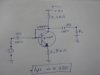
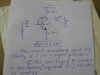
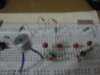
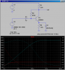
here i have attached a ckt of small signal amplifier which is amplifying very well if the input is given from signal generator... the signal is not being amplified if the input is given from small mic (piezoelectric)
U can have a look at it, in the below attachment

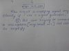
please, suggest me how to amplify it using mic..
with ckt diagram...:confused:

how can distortion be avoided or filtered....
 

Attachments

  • pic char 001.jpg
    pic char 001.jpg
    46.7 KB · Views: 184
  • pic char 002.jpg
    pic char 002.jpg
    75.6 KB · Views: 176
  • pic char 003.jpg
    pic char 003.jpg
    54.4 KB · Views: 192
  • pic char 004.jpg
    pic char 004.jpg
    62.8 KB · Views: 163
Because the emitter resistor is not bypassed with a capacitor, the gain of your amplifier is only ~2.5. To amplify a mic, you will need a gain of > 100.

Look at this simulation of your circuit. The solid red trace is the gain of 8db (2.5) of your amplifier with the emitter bypass capacitor set to 1 femto-Farad, essentially zero. The solid light blue trace shows the gain increases to 44db (158) when the emitter bypass is 47uF. Note that I had to increase the size of the input capacitor to get the amplifier to work down to 100Hz.

Is the mic an electret? If so, you will need a biasing circuit for the mic.
 

Attachments

  • DF171.png
    DF171.png
    42.1 KB · Views: 206
Last edited:
thanks

hi,
thanks no i got it...:)
i don't know what kind of microphone is it
will u be able to tell going through the image attached..
i dint get any specification from the seller....
 
The microphone looks like an electret type, not an old piezo type. Power it with a 10k resistor from +9V. Its metal case is connected to one pin that is the ground (0V) pin.

Since your transistor circuit is extremely simple then it will have plenty of distortion.
You can add a filter that will remove all high audio frequencies if you want. Then everything will sound very muffled.
 
The microphone is electret type .i powered it with a 10k resistor from +9V. Its metal case is connected to one pin that is the ground (0V) pin. now the signal from mic is getting amplified... hi i have used the same bc547 transistor . i din get the one u suggested.... is it possible to feed directly to speaker or a power amplifier is required. and what would be the fm transmitting ckt for this.
 
It is difficult to calculate the gain of the transistor circuit because its input impedance is very low which shorts much of the mic signal.
Of course it cannot drive a speaker.
Its output level might be high enough to feed a power amplifier. Try it.
Most FM transmitter circuits already have a mic preamp transistor.
 
Status
Not open for further replies.

Latest threads

Back
Top