hi all
if someone could answer the following questions that would be great.
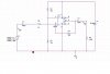
i am trying to make a preamp for a pcb microphone. I am doing some simulations at the mo on orcad and i am having some trouble getting what i require. I found this circuit on the web.
Now i am using a different opamp and DC voltage in the simulation because i dont have the model for the opamp it says to use in the circuit. Anyway i need the circuit to perfrom over the audio range (upto 20khz) and it must run from 3.3V or less. I imagine it will need a failry fast slew rate for audio aswel. If anyone has a good choice please let me know of the IC. the ic from the schematic says to use a TLC727.
Attached is the circuit and time analysis simulation. What i noticed is the output is fairly distorted. Is this becasue of the op-amp? i am assuming it is becasue the 741 is not that fast. Also orcad does not like open ended components therefore the output from the capacitor is tied to ground via a large resistor. Would this cause distortion? in reality i would not include that part if i was to make the circuit. its only for orcads simulation.
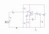
also although the circuit is working i was wondering why the ac signal is not fed into the + terminal of the opamp. Basically a non inverting amplifier and the ac signal fed into the +ve terminal via the two resistors in series. Ive tried that circuit and it didnt work. ive also attached my attempt at the circuit.
thanks
if someone could answer the following questions that would be great.
i am trying to make a preamp for a pcb microphone. I am doing some simulations at the mo on orcad and i am having some trouble getting what i require. I found this circuit on the web.
Now i am using a different opamp and DC voltage in the simulation because i dont have the model for the opamp it says to use in the circuit. Anyway i need the circuit to perfrom over the audio range (upto 20khz) and it must run from 3.3V or less. I imagine it will need a failry fast slew rate for audio aswel. If anyone has a good choice please let me know of the IC. the ic from the schematic says to use a TLC727.
Attached is the circuit and time analysis simulation. What i noticed is the output is fairly distorted. Is this becasue of the op-amp? i am assuming it is becasue the 741 is not that fast. Also orcad does not like open ended components therefore the output from the capacitor is tied to ground via a large resistor. Would this cause distortion? in reality i would not include that part if i was to make the circuit. its only for orcads simulation.
also although the circuit is working i was wondering why the ac signal is not fed into the + terminal of the opamp. Basically a non inverting amplifier and the ac signal fed into the +ve terminal via the two resistors in series. Ive tried that circuit and it didnt work. ive also attached my attempt at the circuit.
thanks