Continue to Site

Welcome to our site!

Electro Tech is an online community (with over 170,000 members) who enjoy talking about and building electronic circuits, projects and gadgets. To participate you need to register. Registration is free. Click here to register now.

  • Welcome to our site! Electro Tech is an online community (with over 170,000 members) who enjoy talking about and building electronic circuits, projects and gadgets. To participate you need to register. Registration is free. Click here to register now.

Slow It Down

Status
Not open for further replies.

ttrezona

New Member
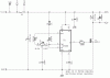
Interested in slowing a motor. I have a roller pump run by a 12 volt motor power by 120 AC to 12V-500 mAmp power supply. It pumps too fast and I want to slow it down by half to two thirds. If I place a Potentiometer in the line to vary the line power output or use a 6Volt 500mAmp power supply my understanding is this will eventually damage the motor. I think I would like to pulse it on and off at full power to control the pump output, like 2 seconds on followed by 3 seconds off, or something similar. However, the pump is turned on by a controller so the power supply will not always be on. Radio Shack does not seem to have any PWM controllers that will do this. Suggestions please.
Tom
 
Hi Tom

It sounds like you want a PWM circuit to control the pump motor speed. This would not be done with seconds on/off but small fractional parts of a second on/off. This link shows an example of what you likely are after. You don't need much as to current. There are several ways to go about PWM and the link shows one popular method.

<EDIT> If you actually want the pump on 3 seconds (or whatever) then off 2 seconds (or whatever) that is a different animal. It can be done but I would not really call it PWM. </EDIT>

Welcome to ETO...

Ron
 
Last edited:
....... This would not be done with seconds on/off but small fractional parts of a second on/off. This link shows an example of what you likely are after.
Ron

hey thanks Ron,

Also found that an interesting. lots of people of electronics forums always talking aby PWM control of motors, I have yet to experiment

now I have a good easy cct diag to try :)

cheers
Dave
 
Thanks Ron. That is excellent. Sound like the pulsing is so fast that it is imperceptible in terms of recognizing on and off. Now here's the next problem. I'm a cancer surgeon not a circuit board surgeon. Where do I buy this device for $10? The people at Radio Shack have never heard of PWM.
 
There was a time when the people at Radio Shack would have known all about PWM but those days are long gone. While the Internet is loaded with circuits to PWM small DC motors I don't know of any complete kits or manufactured circuit boards out there. The last little PWM circuit board I salvaged was out of a small magnetic stirrer system. Maybe a Google of PWM Kits or PWM motor controller will give some results.

Unfortunately I just got some bad news so my visits to the forums might be limited for the next week or so. Just would not want anyone to think I am ignoring their post.

Ron
 
Hi ttrezona,

also a welcome from me to you.

If your project isn't urgent I will sit down and use an already available PWM circuit (or design another one) and design a PCB layout for you.

You might then build the circuit on a board.

You have several options:

A) toner transfer: The image of the PCB is printed on glossy paper using a laser printer. Then the paper is fixed onto a clean copper clad board and the toner ironed to the copper layer. Using laminator the result will be better than using an iron because of equally distributed heat. Heat will melt the toner and transfer it to the copper clad.

B) photo transfer: The image is printed onto a transparent foil which is used to transfer the image on UV-sensitive PCB material. That method requires photo equipment like an UV-exposure box and developer.

A and B require an etchant like ferric chloride to etch excessive copper off the copper clad to leave pads and traces for further processing (drilling)

C) the cheapest method - strip board: Plan thoroughly where the strips need to be interrupted to avoid shorts and solder components in place connecting them with insulated wire

D) Using a friend: If you have a friend who is into electronics he will have the equipment to make a printed circuit board. Knock his door with your foot (hands are occupied with a case of beer) and ask him for the favor to make a PCB for you. :)

I need some more info about your pump motor to make the circuit properly without overkill concerning the power driver.

- nominal and maximum operating voltage and current.

Boncuk
 
Last edited:
Thanks for your help with this Boncuk. The motor is 12 volt and full power is 500 mA. What other info would you need?
 
I would recommend going with a kit, unless you have some experience in soldering and making PCB's. You can look at some of the threads on making PCB's and see that it is not completely trivial for someone who has not done it before. Here are some links (there are many) that have both DIY kits as well as pre-assembled units. Remember, you need something that will handle 12V. The current rating really doesn't matter so long as it is more than 0.5 A. That is, a 10-amp controller will still only provide what your motor needs.

https://www.dhgate.com/12v-24v-3a-d...m-hho/p-ff808081317fdb680131821f26066bcb.html

**broken link removed**

John
 
A roller pump? Is that the kind that they use for pumping blood in dialysis machines or pumping model airplane fuel?

You might try limiting the pumping action with a fluid valve control on the input side. That is an alternate method if you can't find or don't want to use an electronic controller.
 
Last edited:
Yes it is. It uses 1/4" rubber line fixed in a round housing that is compressed by 3 rollers so that the line is always compressed. It feeds to 1/8 tubing on the outflow side. You cannot restrict the input or the output.
 
Hi Tom,

you might want to build your own circuit.

Here is a suggestion:

Duty cycle varies from almost zero to almost 100%. With the pot wiper at center position the duty cycle is exactly 50%.

If you don't have tools to create a PCB you might build the circuit on a strip board.

If you want to make a PCB just PM me your email address leaving your full name (for the contact list for easy relocation).

Here are some screenshots.

That circuit will last forever with a power transistor able to switch loads up to 30A.

Regards

Hans
 

Attachments

  • PWM-SLOW.gif
    PWM-SLOW.gif
    19.3 KB · Views: 132
  • PWM-SLOW-SCOPE.gif
    PWM-SLOW-SCOPE.gif
    61.1 KB · Views: 129
  • PWM-FAST.gif
    PWM-FAST.gif
    18.4 KB · Views: 151
  • PWM-FAST-SCOPE.gif
    PWM-FAST-SCOPE.gif
    60.8 KB · Views: 119
  • PWM-02-SCH.gif
    PWM-02-SCH.gif
    16.9 KB · Views: 127
  • PWM-02-BRD.gif
    PWM-02-BRD.gif
    25.5 KB · Views: 140
  • PWM-02-POUR.gif
    PWM-02-POUR.gif
    28.8 KB · Views: 141
Last edited:
On eBay there are 3A motor controllers which will be plenty for you for AU$12.40 delivered.

No guarantees on the reliability though but they look reasonably well built.

Have a look at this one.
 
Status
Not open for further replies.

New Articles From Microcontroller Tips

Back
Top