Continue to Site

Welcome to our site!

Electro Tech is an online community (with over 170,000 members) who enjoy talking about and building electronic circuits, projects and gadgets. To participate you need to register. Registration is free. Click here to register now.

  • Welcome to our site! Electro Tech is an online community (with over 170,000 members) who enjoy talking about and building electronic circuits, projects and gadgets. To participate you need to register. Registration is free. Click here to register now.

single voltage source equivalent of multiple voltage sources

Status
Not open for further replies.

sstimuluss

New Member
Hi, I've asked this question before re a project, however the discusion was side-tracked, so would like to ask again. Please, I would really appreciate it if someone could explain how this could be implemented, or why it isn't possible.

I have multiple identical resistive touch-switch circuits. They each draw about 60mA max (basically driving LED's).
They are to be operated simultaneously by the same person
If the circuits share one 9v supply, the current running to the touch switches is shared and divided.
If each touch circuit has its own 9v supply, the current doesnt seem to be shared.
Why is this?
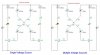
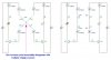
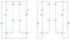
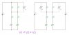
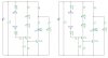
I've tried to illustrate with simple circuit diagram below. Skin resistance values are arbitrary.

My question is _not_ regarding touch switches per se, but rather how to create multiple voltage sources with one voltage source so that current is not crossing over in the skin "resistor bridge".
Please help :confused:
 

Attachments

  • single vs multiple.jpg
    single vs multiple.jpg
    50.7 KB · Views: 393
It matters for my application because with each touch switch the amount of touch (ie. resistance at skin contact point) controls the amount of current running through the LED, ie. brightness. This brightness in turn affects a light dependent resistor, which in turn affects a midi controller value.

If the touch circuits are run off the same voltage source, touching one switch, and then simultaneously touching another, affects the brightness (and therefore midi controller values) of the first switch.
If the touch circuits are run off seperate voltage sources, then more than one can be operated by the same person without affecting one another.

I call them touch switches, but they are really acting as variable resistors where amount of skin contact at each electrode affects resistance.
 
I don't know how you determined the currents in your diagram, but 9 volts is 9 volts, it does not matter if it is one source or two. In order for the currents to be different, there has to be more in the circuit than is shown.
 
Nope, the currents are calculated with TinaPro DC circuit emulation.
I've also tried this on the breadboard.

I'm guessing the reason they differ is that the skin acts as resistor bridge, so with one voltage source, the resistances representing contact with V+ act as one, and thus the current is split at the skin's central point.
 
hmmm.. well thanks for trying it out on your sim.. are you sure you had the exact same circuits? My simulations match what happens on the breadboard when I build the two circuits.

I don't just have two supplies in parallel, the sub-circuits are seperately powered and the only place they meet is in the skin.

If you try it on the breadboard(if you have time that is :), you'll see what I mean. With one supply, touching one affects the other, with separate supplies, they dont.
 

Attachments

  • multiple expanded.jpg
    multiple expanded.jpg
    50.5 KB · Views: 193
My simulatorgives me an error message if I don't have a ground in each independent circuit in the schematic. Try adding grounds on your emitters and see if the simulator gives you more believable results.
 
ron H - i tried your suggestion, and see that it changes the relationship between currents running to the two bases, but I don't understand why you would have a common ground for two circuits running off seperate batteries

regardless of what sims are doing with those circuits, try building it.. you will see.. I'm not just being stubborn, I've actually tested this out, but don't understand it all that much.
 
sstimuluss said:
ron H - i tried your suggestion, and see that it changes the relationship between currents running to the two bases, but I don't understand why you would have a common ground for two circuits running off seperate batteries

regardless of what sims are doing with those circuits, try building it.. you will see.. I'm not just being stubborn, I've actually tested this out, but don't understand it all that much.
Have you actually tried building two circuits, and testing those same two circuits first with separate batteries, and then with a common battery?
The reason I ask is that each circuit is dependent on the beta of its transistor. Unless you test the same circuits in both battery configurations, your results would be expected to be different.
Also, can you just draw the circuits without the skin resistors? Just show the contacts, with dashed lines showing where the "skin resistance" will be applied.
 
Last edited:
i cant remember whether i tested this with the same two transistors, but the actual current readings are not that important, more important is that fact that the two touch circuits affect each other when one battery is used.

with one battery, LED1 dims when LED2 is also activated
with two batteries, LED1 stays the same brightness when LED2 is also activated

thanks for taking interest in this btw
 

Attachments

  • single vs multiple 2.jpg
    single vs multiple 2.jpg
    29.9 KB · Views: 202
sstimuluss said:
i cant remember whether i tested this with the same two transistors, but the actual current readings are not that important, more important is that fact that the two touch circuits affect each other when one battery is used.

with one battery, LED1 dims when LED2 is also activated
with two batteries, LED1 stays the same brightness when LED2 is also activated

thanks for taking interest in this btw
I'm guessing it's due to battery internal resistance, which probably goes up as the voltage goes down. What kind of 9V battery are you using?
 
cheap 9v alkaline..

also, the transistors aren't really essential to demonstrate the effect.. the following circuit yields similar ""independance" with seperate batteries, even though the resistors are joined at a common point.

could you please elaborate on how battery resistance relates to this? think i'm missing something fundamental..
 

Attachments

  • single vs multiple simplified.jpg
    single vs multiple simplified.jpg
    23.5 KB · Views: 172
Ron H said:
My simulatorgives me an error message if I don't have a ground in each independent circuit in the schematic. Try adding grounds on your emitters and see if the simulator gives you more believable results.
Good call, Ron. I am sure that if one emitter is grounded and the other is allowed to float, the results will be much different!
 
sstimuluss said:
cheap 9v alkaline..

also, the transistors aren't really essential to demonstrate the effect.. the following circuit yields similar ""independance" with seperate batteries, even though the resistors are joined at a common point.

could you please elaborate on how battery resistance relates to this? think i'm missing something fundamental..
I agree that the 3 voltages will be different in this shematic.
I wonder if your previous schematic (with the transistors and the electrodes) is accurate. Do you have some connection between the two circuits when you touch them?
 
Ron H said:
I agree that the 3 voltages will be different in this shematic.
I wonder if your previous schematic (with the transistors and the electrodes) is accurate. Do you have some connection between the two circuits when you touch them?

I guess you mean the common connection point that exists when one person touches all four electrodes. This is why I've been representing skin as a four-resistor bridge when dealing with two pairs of electrodes..
 
sstimuluss said:
I guess you mean the common connection point that exists when one person touches all four electrodes. This is why I've been representing skin as a four-resistor bridge when dealing with two pairs of electrodes..
What is the physical arrangement of the 4 electrodes?
 
I didn't concentrate on the circuit to really try and understand it, however I can see that the differences between the two transistors will mess it up, you need a matched pair of transistors.
 
Ron H said:
What is the physical arrangement of the 4 electrodes?

it hasn't _seemed_ to matter all that much how the electrodes are arranged, but basically using large metal plates placed on the floor. the leads connecting electrodes to circuit are quite long, about 4 metres each.

below is the circuit i've been using. one of the 1.8v LED's is mounted inside a small tube, opposite a LDR which affects a midi controller value. the optoisolator outputs are fed into a cmos circuit that eliminates bounce/false triggering and eventually triggers a midi note-on/off. so for each pair of electrodes, closing the circuit with light touch turns a midi note on, and then further contact (more surface area, less resistance) generates midi controller data.

[EDIT: the extra 1.8v LED and 2.2v LED are just indicators.. 1.8v matches whats happening with midi data, and 2.2v is normally on, turning off when a note is triggered]

the reason electrodes are on the floor is that contact dancers are to interact with them, essentially forming human chains between various electrode pairs to generate music, playing on amount of skin contact. but for the purpose of my query as to how to use just one power supply instead of a battery per pair of electrodes without losing the current independance, one only has to consider a single human body making contact with more than one pair of electrodes.
 

Attachments

  • led fader-trigger touch circuit.jpg
    led fader-trigger touch circuit.jpg
    43.4 KB · Views: 341
Last edited:
Hero999 said:
I didn't concentrate on the circuit to really try and understand it, however I can see that the differences between the two transistors will mess it up, you need a matched pair of transistors.

the transistors aren't really the issue, excuse my possible ignorance (still learning :rolleyes: ) I'm sure that matching them would be important somehow, but the problem of current crossing over still remains even without transistors in the circuits.
 
Status
Not open for further replies.

New Articles From Microcontroller Tips

Back
Top