Continue to Site

Welcome to our site!

Electro Tech is an online community (with over 170,000 members) who enjoy talking about and building electronic circuits, projects and gadgets. To participate you need to register. Registration is free. Click here to register now.

  • Welcome to our site! Electro Tech is an online community (with over 170,000 members) who enjoy talking about and building electronic circuits, projects and gadgets. To participate you need to register. Registration is free. Click here to register now.

Sine Wave Using Pic

Status
Not open for further replies.
output.JPG
Hi,
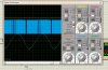
I am trying to Generate sine wave (50Hz) using Pic and I have attached output Wave form and frequency of sine wave seems to be ok round about 50Hz but i am not satisfied with the shape n i dont know where is the mistake in code i am pasting code as well so please help me with this thanks In advance..


Code:
#include<p18f452.h>

#pragma config OSC=HS
#pragma config WDT=OFF
#pragma config LVP=OFF

void init(void);
void timer2_ISR(void);

rom int sine[130]={0,4,8,12,16,20,24,28,32,36,40,44,48,52,56,60,64,68,72,76,80,84,88,92,96,100,104,108
,112,116,120,124,128,132,136,140,144,148,152,156,160,164,168,172,176,180,184,188,192,196,200,204,208,212
,216,220,224,228,232,236,240,244,248,244,240,236,232,228,224,220,216,212,208,204,200,196,192,188,184,180,
176,172,168,164,160,156,152,148,144,140,136,132,128,124,120,116,112,108,104,100,96,92,88,84,80,76,72,68,
64,60,56,52,48,44,40,36,32,28,24,20,16,12,8,4}; //128 Samples

int cnt=0,cnt1=0;
void init()
	{
	INTCONbits.GIE = 1;//Interrupts Enable
	INTCONbits.GIEL = 1;
	INTCONbits.PEIE=1;
	PIE1bits.TMR2IE=1;
	CCP1CON=0b00001100;//PWM Mode
	T2CON=0b00000100;
	PR2=249;//16MHz Crystal And Switching Frequency Is 16KHz
	CCPR1L=0;
	PIR1bits.TMR2IF=0;
	PORTCbits.RC2=0;
	TRISC=0;
	}
//-----------Interrupt---------//
#pragma code low_vector = 0x00018
void low_interrupt(void)
	{
	_asm goto timer2_ISR _endasm
	}
#pragma code
#pragma interrupt timer2_ISR
//----------------------------//
void timer2_ISR()
	{
	T2CONbits.TMR2ON=0;
	CCPR1L=sine[cnt];
	if(cnt1<=16)
		{
		cnt++;
		cnt1=0;
		if(cnt==128)
			{
			cnt=0;
			}
		}
	else
		CCPR1L=sine[cnt];
	cnt1++;
	PIR1bits.TMR2IF=0;
	T2CONbits.TMR2ON=1;
	}
//----------------------------//
void main()
	{
	init();
	while(1);
	}

////////////////
 
Last edited by a moderator:
change the value of the LPF capacitor and resistor, experiment with it and will give you good results.
 
hi
thanks for your reply i cannot understand one thing.
how can we get a pure sine wave out of pic because pure sine wave contains a negative portion and how can we get that negative portion from the above code i m just getting 1 positive half and frequency is double with 128 samples i dont know how to implement other half of the sine in code please anyone help.
Thanks.
 
you cannot obtain a pure sine wave from PIC, only a pseudo sine wave can be done. So if you want pure sine wave do that in some wave form generation IC or something.
 
The sine wave will be between 0 and 5V. To get a sine wave centered about zero would require using an opamp to subtract 2.5V. Alternatively, couple it to the next stage (whatever that may be!) with a capacitor.

Mike.
 
You`re getting a sinewave already.There is nothing that says a sinewave has to be centered around zero. You have a dc shift, because you don't have a bipolar supply (PICs can only operate on positive supply). You would have to shift the bias after the PIC output as mentioned before. As for the frequency, if you're at half frequency then either increase your PIC clock frequency by 2 , or half the number of points on the table (that u fix in code).
The only thing u control with the rc is how much filtering (smoothing) the sinewave gets.
 
how can we get a pure sine wave out of pic because pure sine wave contains a negative portion and how can we get that negative portion from the above code

As others have said, a sinewave (or any other shape) doesn't have to be centred on zero - if you want it to be?, simply pass it through a DC blocking capacitor with a 'load' resistor to 0V.

Also as has already been said, you need a suitable LPF on the output to smooth it to a good smooth sine shape.

However, if you mentioned what you're trying to do, you might get better advice?.
 
Capture.JPG

Thanks Alot EveryOne.

Here is what i am getting a nice sine wave centered at zero now i want to step this up to 220 using transformer and kindly help me building a filter where should i use filter at the primary side or at the final stage and which filter is better RC or LC i am not too good at power electronics stuff so please help me making this and what will be the side effect if i use 56Hz instead of 50Hz on Appliances is it a big difference as it would cause change in impedance please Help.
Thanks in Advance....
 

Attachments

  • Capture.JPG
    Capture.JPG
    99.5 KB · Views: 653
Last edited:
If you want an exact 50Hz sinewave for inverter use with a transformer, there are a couple of tested projects with source code and schematics on this page;
https://www.romanblack.com/one_sec.htm

(see "Accurate xtal-locked Sinewave inverter!" about 3/4 of the way down the page.) It does not need a low pass filter as the transformer does that job, the PIC drives two FETs which apply two complementary PWM sinewaves directly to the two transformer windings.

You will need to fiddle with the "sine" table values, when I built one using perfect sine values at the PIC, the wave out of the transformer was not particularly sine like. I was able to tweak the sine table values later to get a pretty good mains sinewave out of the transformer with a bit of trial and error.
 
Status
Not open for further replies.

New Articles From Microcontroller Tips

Back
Top