I need to generate a 5V power-level sine-wave that will be stepped up by a transformer to drive an electrostatic ultrasonic transducer. Normally I'm pretty think I could just drive a square directly into the transformer at the fundamental and just send that and detect the fundamental as it comes back. I'm trying to make a crude doppler though, so I need the transmitted wave to be as clean a sinusoid as possible so I can tell if a frequency shift happened (rather than just a bunch of higher harmonics echoing back if it was a square wave).
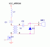
Primary Side:
So...attached is the circuit I was thinking about. I might not need L1 if I just size the capacitor to work with the transformer's primary inductance. A square wave is driven into Q1's gate and the bandpass filtering of the series L-C resonant circuit *should* filter out the higher harmonics to produce a sinusoid at the fundamental frequency that appears at the drain of Q1 (or across the primary of the transformer...right? Am I missing anything here?
Secondary Side:
I am unsure as to why C2 or D1 is needed (although I suspect it's just AC filtering and voltage clamping for the transducer). I stole that half off of a transduver reference circuit that uses ASICs which was very confusing. THe transducer does need a high-voltage DC bias which does not seem to be supplied by this circuit though so I am not sure how the reference circuit did it (it was all low voltage except for the transformer). I think that C2 and D1 might have some role to play in providing this bias, but I don't understand how it works. I remember seeing the same capacitor-diode configuration on the following app-note with a brief mention of providing a DC bias. It is on 2.1, figure 2:
https://www.electro-tech-online.com/custompdfs/2007/08/fetdrvr-t.pdf
DOes anyone understand what's going on?
EDIT: Oh, for the receiver portion I was going to add a diff-amp across the transformer primary to refer the signal to ground, run in through an amp, and then split it up through a series of bandpass filters whose frequencyes would represent various discrete speed ranges of the object, so that with the time-of-flight being measured on each bandpass channel, you could figure out how far a series of targets was away, and the speed that they were coming towards you at. It's pretty crude, but I don't have the memory available on my processor to sample the entire received signal and then do fourier on it. Does anyone have any better ideas?
AT the maximum speeds I am intersted in, there is just a 500Hz shift. I can probably transmit much more accurately than this since it's the square deciding the frequency and the transmit LC filter isn't too critical of this. I'm not sure if the analog filters in the receive circuit can differentiate 500Hz though, let alone the smaller increments I need to have speed ranges.
Attachments
Last edited:
