wizard
Member
Hi,
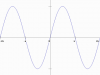
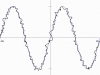
Today when someone asked me something about sine waves, we went for a way to see what job we have to do to get a signal like the bellow picture(the second)?
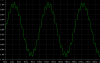
I mean suppose you have a pure sine wave(the first pic) and you want to get a wave form like the second by putting another small signal on pushes of the sine wave(like the second raw picture which I have drawn using Microsoft paint)
How to do that? what we can call the second signal? Is it related to modulation? Is it kind of modulation or if it has any special name in Electronics? Is it use in Electronics anyway?
Thanks
Today when someone asked me something about sine waves, we went for a way to see what job we have to do to get a signal like the bellow picture(the second)?
I mean suppose you have a pure sine wave(the first pic) and you want to get a wave form like the second by putting another small signal on pushes of the sine wave(like the second raw picture which I have drawn using Microsoft paint)
How to do that? what we can call the second signal? Is it related to modulation? Is it kind of modulation or if it has any special name in Electronics? Is it use in Electronics anyway?
Thanks