Continue to Site

Welcome to our site!

Electro Tech is an online community (with over 170,000 members) who enjoy talking about and building electronic circuits, projects and gadgets. To participate you need to register. Registration is free. Click here to register now.

  • Welcome to our site! Electro Tech is an online community (with over 170,000 members) who enjoy talking about and building electronic circuits, projects and gadgets. To participate you need to register. Registration is free. Click here to register now.

Simulation of an FM Transmiter.

Status
Not open for further replies.

iyke20024

New Member
Dear Friends,

I need an asistance in making my project of FM Transmitter to work.. Can someone help me out here, as i need to make it work in 2 weeks time.

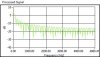
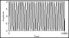
I have actually made some effort and come up with an output signal but needs to verify if i am on the right track. I am not even seeing the actual modulated signal..
Moreover, the frequency deviation is more than the normal standard deviation for FM signal.

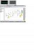
Another problem is my carreer frequency.... When i calculated the theoretical values and compared to my actual value from my simulation in my tank circuit. it was totally different

Thank you for your anticipated help
 

Attachments

  • image2.jpg
    image2.jpg
    308.9 KB · Views: 126
  • image.jpg
    image.jpg
    19.3 KB · Views: 119
  • image1.jpg
    image1.jpg
    21.5 KB · Views: 116
Can you turn off the dots that are all over your schematic?

Your microphone signal is 4V p-p which is nearly 800 times too high. Turn down the level. It is saturating and cutting off the oscillator transistor which might change its frequency.

Stray capacitance of the parts and their wires nearly double the amount of total capacitance in this very high frequency circuit that your calculations do not account for so of course the actual frequency is much lower than calculated. It won't work if you make it on a breadboard, a compact pcb or stripboard must be used.

Thank for you time...

I have cut down the peak to peak voltage of my microphone...to 80mv..
Below you will find the modulating signal..

Stray capacitance of the parts and their wires nearly double the amount of total capacitance in this very high frequency circuit that your calculations do not account for so of course the actual frequency is much lower than calculated.

Are you saying that my electrical connections affects my capicitance so i could not get the actual caculated frequency. How could i solve this problem... I am not actually constructing this circuit... I was required to verify (frequency deviation.... and others..) and simulate the circuit with the aim of arriving at a desired modulated signal.

22% of 33pf as in my tank circuit.... does not actually gives the actuall capacitor value... is it actually 22% of the variable capacitors value...?

I am kind of new to electronics...

Thanks audioguru..
 

Attachments

  • image3.jpg
    image3.jpg
    231 KB · Views: 115
Status
Not open for further replies.

Latest threads

New Articles From Microcontroller Tips

Back
Top